Before World War II the FM radio band was just below 50 Mc. Read all about it. If you have such a radio, you might want to build this converter. It will let your old set receive the modern FM band (88 to 108 Mc.). This design is based on an article I wrote for Radio Age.
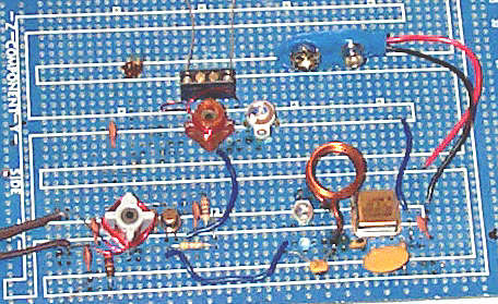
Larry Gagnon built one of these for his Zenith console. He sent me this photograph and said it works very well for him.
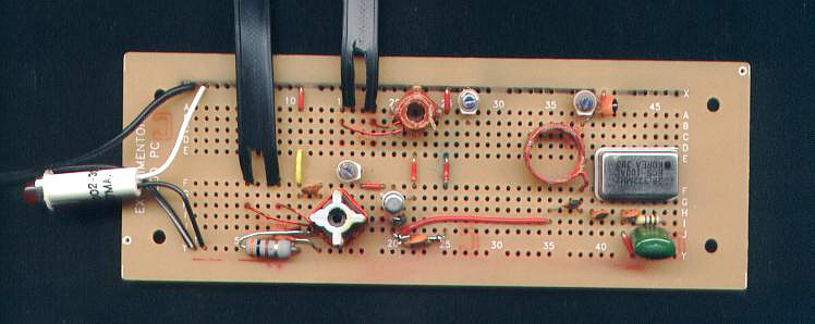
Except the the circuit board and battery, all parts are from Mouser Electronics. A complete parts list with stock numbers is listed below. I built this on a perforated board with solder pads. Radio Shack sells these boards for a reasonable price. A plain piece of perforated board will also work.
Layout should follow the schematic. L1 should be between OSC1 and Q1. T1 should be on the other side of Q1. T2 should be off to the side of Q1.
You must wind L1 yourself. Use any cylindrical object that is just under 1/2 inch in diameter. I used a thick pencil from my son's grade school class, but a magic marker or a large drill bit will work just fine. Wind 6 turns with #18 or #20 wire. Wind the wire tightly on the cylinder and then slip the wire off. Mount the ends of the wire on your circuit board keeping some clearance between the coil and the circuit board.
T1 and T2 are constructed by adding windings to the commercial coils. Use #24 or #26 magnet wire. T1 uses 7 turns of wire wrapped around the middle of the existing coil. This new winding is the output to the pre-war FM radio. T2 is a bit different. Trim off each of the four plastic ribs above the windings of the coil so you can add windings along side of the existing ones. Add a 4 turn winding just above the existing coil. This new winding goes to the 88 Mc antenna.
Adjustment is critical for proper operation. If you can hear a FM station at all, then you can simply try to adjust for best signal. L1 will have no obvious effect. Here is the preferred method of adjustment.
Tune a receiver to 85.0 Mc and connect it to the output of the converter. This frequency is the third harmonic of the 28.322 Mc. oscillator. Adjust C9 for minimum signal. You may need to solder a 10pf capacitor in parallel with C9 to get good attenuation of the 85 Mc signal. This signal will never go to zero; the goal is to reduce it by 10 to 20 dB.
Tune a receiver to 45.0 Mc and connect it to the output of the converter. Inject a 45 Mc signal into the input of the converter. Use shielded wires if possible so that the receiver only picks up signals passing through the converter. Adjust C5 and T1 for maximum received signal.
Keep the receiver at 45.0 Mc and inject a 96.61 Mc signal. Adjust C10 and T2 for maximum received signal.
Click here for a PDF version of the schematic
All parts can be obtained from
Mouser Electronics
www.mouser.com
sales@mouser.com
1-800-346-6873
| C1,C2,C4,C8 | 0.001 uf, 50 v, ceramic disc capacitor | 140-50P2-102K |
| C3 | 0.1 uf, 50 v, film capacitor | 140-PF1H104K |
| C5,C9,C10 | 3.5 - 20 pf trimmer capacitor | 24AA022 |
| C6,C7 | 10 pf, 50 v, ceramic disc capacitor | 140-50N5-150J |
| Q1 | 3N204 or 40673 | 570-3N204 |
| R1 | 470, 1/4 w, resistor | 291-470 |
| R2 | 300, 1/4 w, resistor | 291-300 |
| R3 | 47K, 1/4 w, resistor | 291-47K |
| R4 | 120, 1/4 w, resistor | 291-120 |
| L1 | 6 turns of #20 wire | see text |
| T1 | .38uf coil with 7 turn link | 434-1012-8.5C (see text) |
| T2 | .12uf coil with 4 turn lik | 434-1012-3.5C (see text) |
| battery connector | mini battery snap | 12BC025 |
| OSC1 | 28.322 Mc oscillator | 520-TCF2832 |
[HOME] [FM list] [Photos] [Converters] [Stereo] [Wanted] [Links] [Credits] [Clones] [Siblings] [Low Tech] [FM vs AM]
Last updated 3 September 2010
Original site located at http://www.somerset.net/arm/fm_only.html by Andrew R. Mitz ; copied with permission.
(Mirror maintained by Mark Sherman)
m@mwsherman.com
All circuits, text, photographs, and other graphics are copyright (c)
1998- 2010 LTJ Designs.