Build A One Transistor FM Radio
updated designs!
|
See below for:
My new, improved
One Transistor FM Radio
|
|
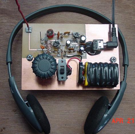
Build
this one transistor FM radio
(my design)
Enlarge: [medium] [large]
|
or
Build this one transistor FM radio
(Designed by Patrick Cambre)
Enlarge: [large]
There is a newer version if you can find on Patrick's web site
|
My Design
A printed circuit board for the original circuit is available
through FAR Circuits. Ask them for "Andy Mitz's One transistor FM radio printed circuit
board". The circuit board must be modified for the improved
one transistor radio.
Introduction
AM radio circuits and kits abound. Some work quite
well. But, look around and you will find virtually no FM radio kits.
Certainly, there are no simple FM radio kits. The simple FM radio circuit
got lost during the transition from vacuum tubes to transistors. In the
late 1950s and early 1960s there were several construction articles on building
a simple superregenerative FM radio. After exhaustive research into the
early articles and some key assistance from a modern day guru in regenerative
circuit design, I have developed this simple radio kit. It is a remarkable
circuit. It is sensitive, selective, and has enough audio drive for an
earphone. Read more about theory behind this radio on the
low-tech FM page.
Construction
parts source
Except the the circuit board and battery, all parts are from Mouser
Electronics. A complete parts list with stock numbers is listed below.
The circuit board is available through FAR
Circuits. The variable capacitor is available through Electronix
Express.
layout
Because this is a superregenerative design, component layout can
be very important. The tuning capacitor, C3, has three leads. Only
the outer two leads are used; the middle lead of C3 is not connected.
Arrange L1 fairly close to C3, but keep it away from where your hand will
be. If your hand is too close to L1 while you tune the radio, it will make
tuning very difficult.
winding L1
L1 sets the frequency of the radio, acts as the antenna, and is
the primary adjustment for super-regeneration. Although it has many
important jobs, it is easy to construct. Get any cylindrical object that
is just under 1/2 inch (13 mm) in diameter. I used a thick pencil from my
son's grade school class, but a magic marker or large drill bit work just
fine. #20 bare solid wire works the best, but any wire that holds its
shape will do. Wind 6 turns tightly, side-by-side, on the cylinder, then
slip the wire off. Spread the windings apart from each other so the whole
coil is just under an inch (2.5 cm) long. Find the midpoint and solder a
small wire for C2 there. Mount the ends of the wire on your circuit board
keeping some clearance between the coil and the circuit board.
a tuning knob for C3
C3 does not come with a knob and I have not found a
source. A knob is important to keep your hand away from the capacitor and
coil when you tune in stations. The solution is to use a #4 nylon
screw. Twist the nylon screw into the threads of the C3 tuning handle. The
#4 screw is the wrong thread pitch and will jam (bind) in the threads. This is
what you want to happen. Tighten the screw just enough so it stays put as
you tune the capacitor. The resulting arrangement works quite well.
Adjustment
If the radio is wired correctly, there are three possible things
you can hear when you turn it on: 1) a radio station, 2) a rushing noise,
3) a squeal, and 4) nothing. If you got a radio station, you are in good
shape. Use another FM radio to see where you are on the FM band. You
can change the tuning range of C3 by squeezing L1 or change C1. If you
hear a rushing noise, you will probably be able to tune in a station. Try
the tuning control and see what you get. If you hear a squeal or hear
nothing, then the circuit is oscillating too little or too much. Try
spreading or compressing L1. Double check your connections. If you don't
make any progress, then you need to change R4. Replace R4 with a 20K or
larger potentiometer (up to 50K). A trimmer potentiometer is best. Adjust
R4 until you can reliably tune in stations. Once the circuit is working, you can
remove the potentiometer, measure its value, and replace it with a fixed
resistor. Some people might want to build the set from the start with a
trimmer potentiometer in place (e.g., Mouser 569-72PM-25K).
Substituting other components
Many of the parts are fairly common and might already be in your
junk box. Only certain component values are critical. The RF choke
should be in the range of 20 to 30 uh, although values from15 to 40 uh might
work. The tuning capacitor value is not critical, but if you use values
below 50 pf you should reduce or remove C1. The circuit is designed for the high
impedance type earphone. Normal earphones can be used, but the battery
drain is much greater and the circuit must be changed. To use normal
earphones, change R3 to 180 ohms. Q1 can be replace with any
high-frequency N-channel JFET transistor, but only the 2N4416, 2N4416A, and J310
have been tested. A MPF102 probably will work. C2 is not too critical;
any value from 18 to 27 pf will work. C7 is fairly critical. You can use a
.005 or .0047 uf, but don't change it much more than that.
Improved design for more audio gain
Chris Iwata recommended some design changes that greatly improve
the audio circuit, making it strong enough for regular earphones or even a small
speaker. The same FAR printed circuit board can be used with some
modifications. The circuit board is important to make sure the tuning end of the
radio works properly, so the audio amplifier changes can be squeezed onto the
circuit board without fear of wrecking radio operation. Look closely at
the new schematic for the new components and some changed component values.
Schematic diagram for the Original One Transistor FM Radio
Click here for a PDF
version of the schematic. You can also make this
into a simple CB radio receiver. See this
PDF file.
Schematic diagram for the One Transistor FM Radio with Improved
Audio Gain
Click here for a PDF
version of the schematic.
One Transistor FM Radio with improved audio gain.
Printed circuit board
The printed circuit board for the original One Transistor FM Radio is available
through:
FAR CIRCUITS
Printed Circuit Boards
18N640 Field Court
Dundee, Illinois 60118
(847) 836-9148 Voice/Fax
Some wiring notes:
-
Unless you have experience with super-regenerative radios, I
highly recommend using the FAR Circuits printed circuit board.
-
Connect the two sections of the variable capacitor (C3) in
series to linearize the tuning somewhat. That is, use the connections
on either end of C3 and don't use the middle lead.
-
L2, the RF choke should not be near a ground. The same is
true for L1. Capacitance to ground will disturb the feedback.
The gain is just enough to drive an earphone. If you live too far away from
radio stations, you might have trouble hearing one. There is no option
here for an external antenna (that would require and extra transistor).
-
You can drive a speaker if you add an external audio
amplifier.
-
If you want a little more audio gain, or you cannot locate a
TL431CLP chip, you can use some other audio amplifier in the circuit where
pins 1 and 2 of D1 normally connect. You can use an LM386 or a TDA7052 audio
amplifier.
Parts list for original circuit (see schematic of the improved
version for new part values)
All parts except the RF tuning capacitor can be obtained from
Mouser Electronics
www.mouser.com
sales@mouser.com
1-800-346-6873
The RF tuning capacitor can be found on eBay
| Part designator |
Part description |
Vendor stock number |
| C1a,C1b |
10 pf, 50 v, ceramic disc capacitor |
140-50N5-100J |
| C2 |
22 pf, 50 v, ceramic disc capacitor |
140-50N5-220J |
| C3 |
RF tuning capacitor |
N14VCRF10-280P |
| C4 |
330 pf, 50 v, ceramic disc capacitor |
140-50P2-331K |
| C5,C8 |
0.001 uf, 50 v, ceramic disc capacitor |
140-50P2-102K |
| C6 |
0.22 uf, 50 v, film capacitor |
140-PF1H224K |
| C7 |
0.0047 uf, 50 v, ceramic disc capacitor |
140-50P5-472K |
| C9 |
22 uf, 16 v, electrolytic capacitor |
140-XRL16V22 |
| D1 |
TL431AIZ voltage control Zener (shunt regulator) |
511-TL431AIZ |
| EPH1 |
High impedance earphone |
25CR060 |
| L2 |
22 uh RF choke |
542-70F225 |
| Q1 |
2N4416A JFET transistor |
510-2N4416A |
| R1 |
470K, 1/4 w, resistor |
291-470K |
| R2, R3 |
1K, 1/4 w, resistor |
291-1K |
| R4 |
10K, 1/4 w, resistor |
291-10K |
| R5 |
1M, 1/4 w, resistor |
291-1M |
| R6 |
100 ohm, 1/4 w, resistor |
291-100 |
| S1 |
Small SPST switch |
10SP003 |
| screws for C3 |
screws for mounting C3 (2 needed) |
48SS03 |
| nylon screw |
#4 nylon screw used for tuning C3 |
561-T0440037 |
| battery connector |
mini battery snap |
12BC025 |
[HOME]
[FM list] [Photos]
[Converters] [Stereo]
[Wanted] [Links]
[Credits] [Clones]
[Siblings] [Low
Tech] [Tubes] [FM
vs AM]
Last updated 27 March 2013
Original site located at http://www.somerset.net/arm/fm_only.html by Andrew R. Mitz ; copied with permission.
(Mirror maintained by Mark Sherman)
m@mwsherman.com
All circuits, text, photographs, and other graphics are copyright (c)
1998-2013 LTJ Designs.
![[medium]](reprints/simplefm_photo_medium.jpg)
![[large]](reprints/simplefm_photo.jpg)
![[large]](reprints/radio_shack_special/rss1_big.jpg)