 |
This project is
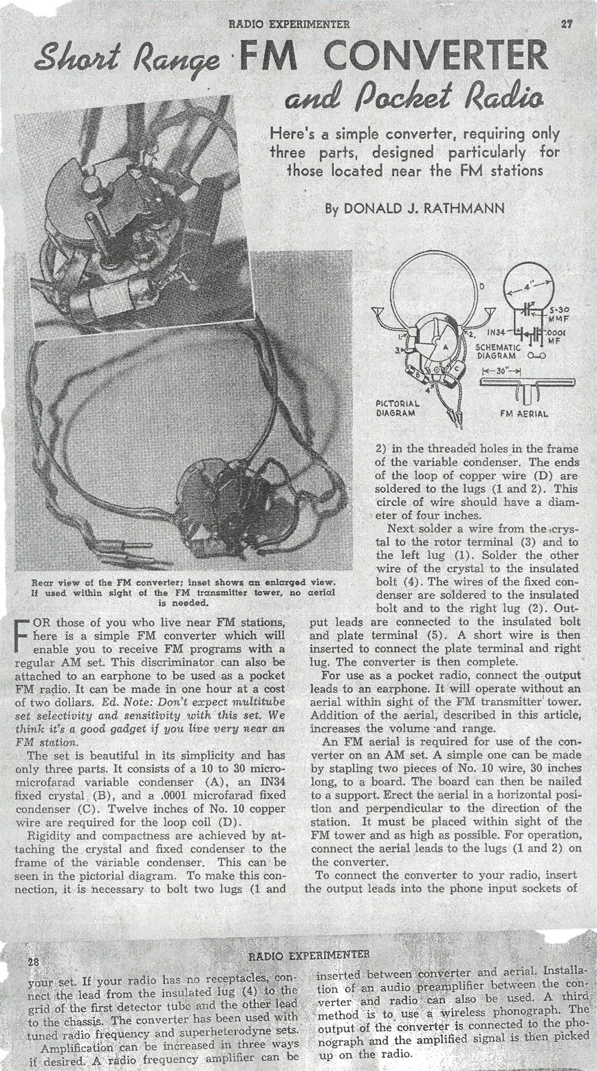
from the Fall 1947 issue of Science and Mechanics Radio and TV Experimenter.
Click on the figure to see the full article
(Thanks to BILL TURNER for finding this article.) |
[Theory] [Projects] [Commercial Examples]
Broadcast band frequency modulation (FM) radio was invented to solve existing problems with noise and fidelity on the amplitude modulation (AM) broadcast band. Thus, the first FM receivers were quite complex in design, employing a superheterodyne converter, a wideband IF, a limiter stage, and a discriminator. Unlike the first AM radio sets, the earliest FM radio sets did not use the simplest possible methods for receiving signals. Perhaps Armstrong, the inventor of most modern radio methods, was fully aware of all the ways to receive FM. (Someone reading these comments might want to offer the technical history so I can add it here.) But, it was not until much after the introduction of commercial broadcast FM that simple FM receiver designs were published or sold.
Although the title alludes to simplicity, these radio designs are not uniformly simple. These designs generally have low component counts, however the design or construction my have been far from simple.
Believe it or not, you can actually make an FM radio crystal set. The key to understanding how this simple circuit can decode FM is to understand what happens when an FM signal is coupled to a tuned circuit. A good tuned circuit (one with a high "Q factor") will attenuate signals that are not near its resonant frequency. If you apply a FM signal to a good tuned circuit, as the frequency of the FM signal moves away from the resonant frequency of the tuned circuit, the tuned circuit will attenuate that signal. As the frequency of the FM signal moves toward the resonant frequency of the tuned circuit, the tuned circuit will let more of the signal pass through. Thus, a tuned circuit will impose amplitude changes on a FM radio signal that match the frequency changes. A crystal diode is sensitive to amplitude changes, so it converts the amplitude changes into a signal that the listener can hear through headphones.
Using a tuned circuit to induce amplitude changes onto an FM signal, then converting the amplitude changes to sound frequencies, is called slope detection. "Slope" refers to the slope of the tuned circuits' attenuation curve. If you have an AM receiver, you can listen to a FM signal by using the slope of the tuned circuits in the receiver. This method gives you none of the real advantages of FM. For instance, FM is noted for its immunity to static. An AM receiver used to slope detect will hear static. The only real advantage to slope detection is that is can be cheap and convenient. When tuning in an FM signal with an AM receiver, the clearest sound occurs when the FM center frequency is offset from the center frequency of the receiver's tuned circuits. If the FM signal is at the receiver's center frequency, then frequency deviations both up and down produce downward amplitude changes. When the FM signal is off center, up and down frequency changes create up an down amplitude changes in the receiver.
Believe it or not, an oscillator is an FM detector. If an FM signal is coupled into the tuned circuit of an oscillator, there will be an additive effect between the FM signal and the oscillator's signal when the two match exactly in frequency. This additive effect will show up as slightly stronger oscillator signal amplitude. As the FM signal swings away from this perfectly matching frequency, the additive effect will diminish. Just like with slope detection, the amplitude variations can be used to create an audible signal. The non-linearity of most oscillators will detect the amplitude variations without the need for a diode detector.
One way to maximize the gain of an amplifier is to design a circuit that lets the operator control the gain. With sufficient positive feedback, a circuit can be designed that has lots of gain, but will oscillate if its gain is set too high. This type of circuit is called a regenerative amplifier. If a regenerative amplifier includes a high Q tuned circuit, then that amplifier can act as a regenerative detector for FM. Regenerative detectors can be quite inexpensive, easy to assemble, and give surprisingly good results.
The superregenerative detector is an amazing circuit invented by Armstrong that uses a superregenerative amplifier. Understanding a superregenerative amplifier is a bit involved. There are two basic types, self-quenched and externally-quenched. Don't worry about the terminology; I simply want to state that this discussion is for the self-quenched type.
Here is how you make a superregenerative circuit. Choose a regenerative amplifier circuit configuration that requires more current during oscillations than when not oscillating. Adjust the regenerative amplifier to oscillate. Add a small circuit that uses the current of the amplifier to charge a capacitor while oscillations are taking place. Once the capacitor is charged, the voltage on the capacitor is used to kill the oscillations of the circuit. (Technically, the capacitor voltage shifts the operating point of the amplifier to reduce its gain and stop the oscillations.) When the oscillations stop, the capacitor discharges (through a resistor). Once the capacitor is discharged, the oscillations begin again.
A superregenerative amplifier thus oscillates at two frequency. It oscillates at the tuned frequency of the amplifier and it has this secondary stop-start-stop-start oscillation. If the primary oscillation is at 100 MHz, the secondary should be at about 30 KHz for optimal performance.. (Please email me if you have detailed technical information on this frequency relationship.) Note that the 30 KHz is above audio frequencies, so the listener does not hear any noise associated with either oscillation. The superregenerative technique does not work well at lower radio frequencies because the optimal frequency of the secondary oscillation ends up in the audio frequency range.
To finish, a superregenerative FM detector is simply a tuned superregenerative amplifier used to listen to FM. Note, because this circuit oscillates, it can cause interference with nearby receivers. There are ways to avoid this interference. Also note that a superregenerative detector can be the basis of an very simple, very effective FM radio.
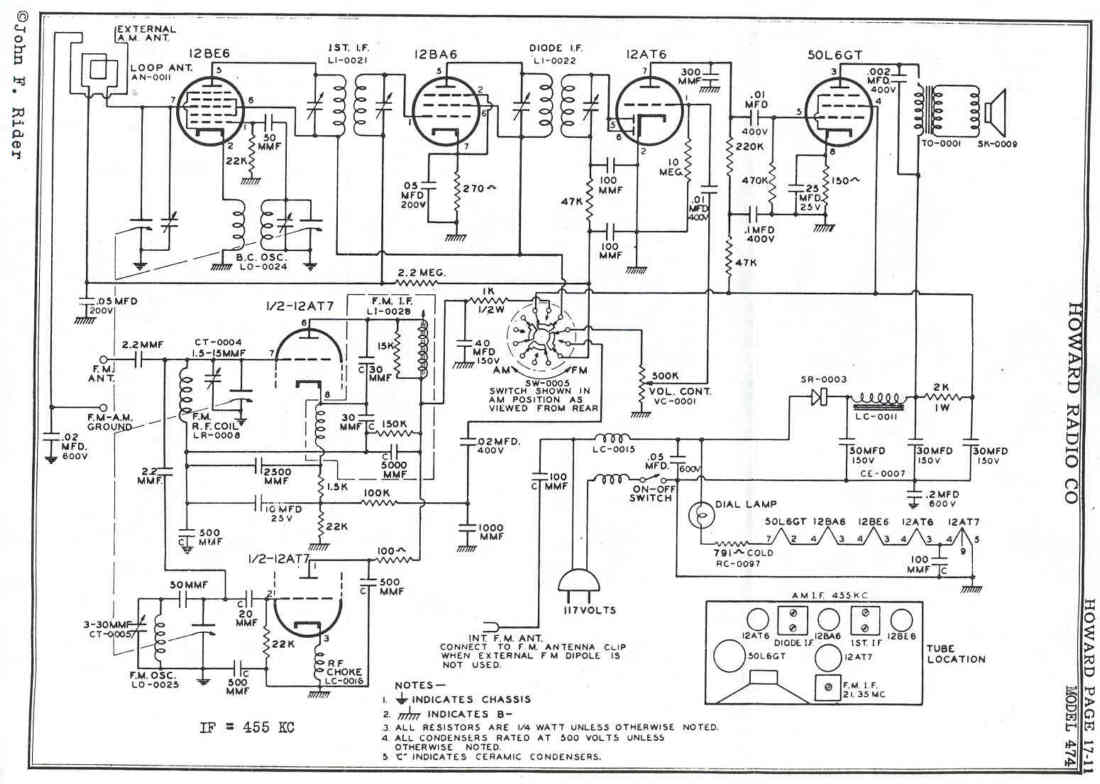
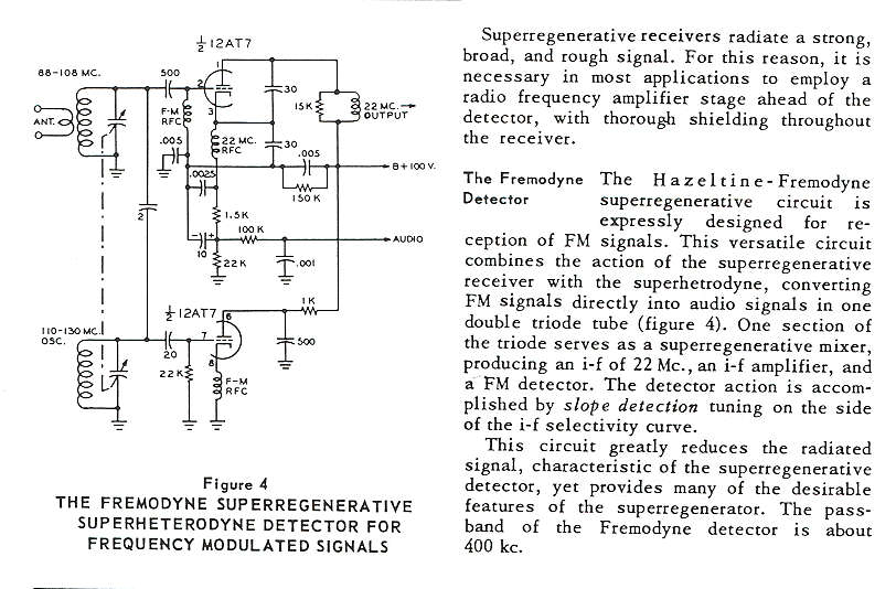
One major problem with standard superregenerative detectors is that they generate interference. They oscillate on the radio frequency that, perhaps, other receivers are trying to receive. Moreover, the antenna coupling circuit and antenna are both tuned to the frequency of oscillation. One clever solution to this interference problem is the Hazeltine-Fremodyne circuit. With this circuit, the input is tuned to the FM station. The superregenerative detector is tuned to another frequency, typically 22 MHz. A local oscillator tuned 22 MHz above the FM signal injects a carrier into the grid of the detector. The superregenerative circuit acts as a mixer, amplifier, and FM detector. Its oscillations are not near the resonant frequency of the input tuned circuit or antenna, so interference is substantially reduced.
Frequency to voltage converters are used in some simpler FM receiver designs. The voltage coming out of the limiter is converted to uniform size pulses. These pulses are delivered to a "leaky integrator," made of a capacitor that is charged by each pulse. A resistor in parallel with the capacitor continuously discharges (leaks) the capacitor voltage. When the pulse rate is above a critical frequency, the pulse train increases the capacitor voltage; below this frequency, there is a net loss of voltage. The capacitor voltage is always proportional to the pulse train rate. This method was used in a FM tuner design found in the GE Transistor Manual (e.g., 17th edition).
Phased FM detection is used in complex receivers, and is also used in transmitters. The quadrature detector splits a FM signal into two pathways, and phase shifts each path so that a 90 degree phase difference exists between the two signals. The two signals are fed into a balanced modulator. FM signals (or phase modulated signals) mix in the modular and, because they are 90 degrees out of phase from each other, produce an amplitude variation that is proportional to modulation frequency. The only reason phased FM detection is included here under "simple" FM detection, is that Ed Richley has published an article on building a phased FM crystal set. The article appears in Volume 6, No. 1 (issue #28, January 1996) and No. 2 (issue #29, March 1996) of The Xtal Set Society Newsletter. This article is available here by permission of both the author and the XSS editor: page [1] [2] [3] [4] [5] [6] [7] [8].
Simple tuner design from 1947
|
This project is
from the Fall 1947 issue of Science and Mechanics Radio and TV Experimenter.
Click on the figure to see the full article
(Thanks to BILL TURNER for finding this article.) |
Resonant cavity designs
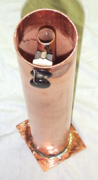 |
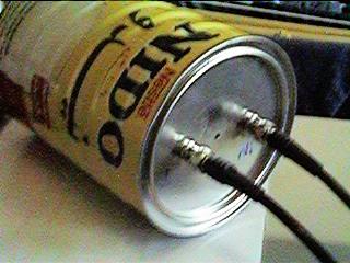
This project comes from the Vacuum Tubes, Inc. website. The tuner uses standard pipes to construct a resonant cavity, which is coupled to a crystal diode through an 1/8 wave coax transformer. Credit for the design is given to Ed Garner. |
|
|
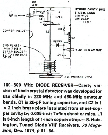
Resonant cavity design from 73 Magazine: Credit is given to: B. Hoisington "Tuned Diode VHF Receivers" 73 Magazine, December 1974, p81-84. However, this page of 73 Magazine is just a list of circuits borrowed from other sources. The original source of this design is unknown.
|
|
|
Resonant cavity design by Harry Lythall: Information (zip file)
|
One-tube FM tuner
 |
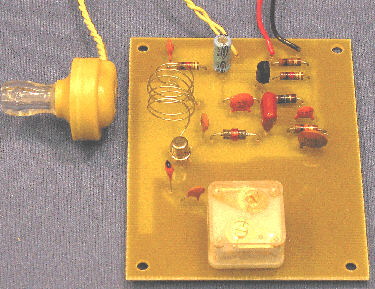
This project
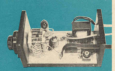
comes from the August 1960 issue of Popular Electronics.
The design uses one 6C4 in a robust superregenerative circuit.
Click here to view the full article: Thanks to Alan Douglas for providing this article and a working model. |
One transistor FM radio
|
|
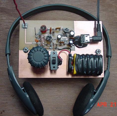
I designed this
superregenerative circuit with lots of help from Charles Kitchin, a real
expert in regenerative radio design. The audio section is stolen
from a web site by Charles
Wenzel; perhaps he designed the circuit as well. This is the
first truly easy-to-build FM radio I have ever seen. The performance is
quite good. It has just the right amount of volume for an earphone
and it does not need an antenna.
Radio schematic: PDF file GIF file Build this project yourself |
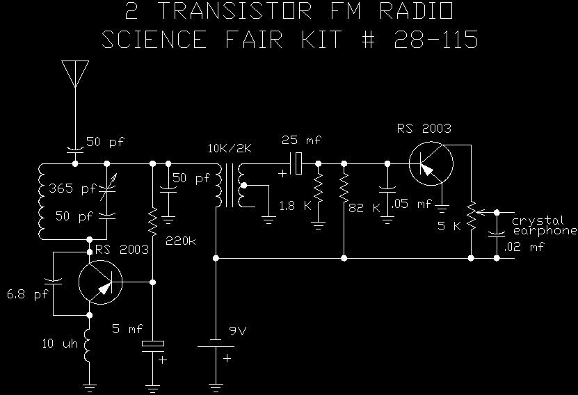
Two transistor Radio Shack Science Fair FM radio kit (circa 1972)
|
|
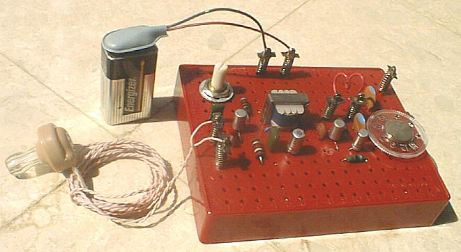
| This
rare Radio Shack FM radio kit is owned by Camil Moujaber, a radio collector and designer. It is one of the
very few FM radio kits designed for children to build. Note that
this design, like mine, does not employ a regeneration control.
Radio schematic: JPEG file
|
The "Radio Shack Special" by Patrick Cambre
|
|
Called the "Radio Shack Special" because Radio Shack sells the MPF102 FET transistor. It uses one transistor and one audio amplifier IC (LM386).
|
Hazeltine-Fremodyne Circuit
|
|
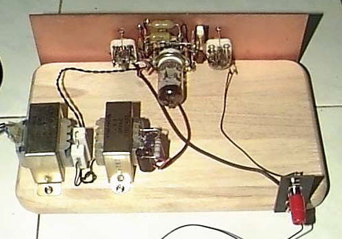
| Home built example of the Hazeltine-Fremodyne circuit using separate tuning capacitors for the local oscillator and the regenerative detector. (Example courtesy of ew c.g.) |
|
|
| John Hunter has a number of interesting FM radio designs and projects on his web page called: Cool386 |
The Howard Model 474: An AM/FM radio that uses a Hazeltine-Fremodyne circuit for FM
|
|
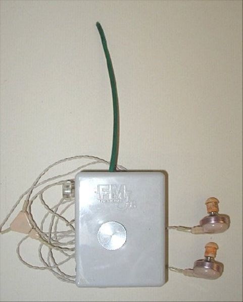
The Hastings FM Jr. from Concert Networks a superregenerative FM pocket tube radio
[HOME] [FM list] [Photos] [Converters] [Stereo] [Wanted] [Links] [Credits] [Clones] [Siblings] [Low Tech] [FM vs AM]
Last updated 27 May 2013
Original site located at http://www.somerset.net/arm/fm_only.html by Andrew R. Mitz ; copied with permission.
(Mirror maintained by Mark Sherman)
m@mwsherman.com
All circuits, text, photographs, and other graphics are copyright (c)
1998-2013 LTJ Designs.
![[1]](reprints/richley_1.gif)
![[2]](reprints/richley_2.gif)
![[3]](reprints/richley_3.gif)
![[4]](reprints/richley_4.gif)
![[5]](reprints/richley_5.gif)
![[6]](reprints/richley_6.gif)
![[7]](reprints/richley_7.gif)
![[8]](reprints/richley_8.gif)
![[1]](reprints/fm_tuner_1.jpg)
![[2]](reprints/fm_tuner_2.jpg)
![[3]](reprints/fm_tuner_3.jpg)
![[4]](reprints/fm_tuner_4.jpg)