Retrochallenge 2018/09, 2019/03
For the Retrochallenge 2019/03, I am continuing the work I started in RC 2018/09 and trying to finish KittyOS into a real operating system, finally making the CAT-644 a real computer.
This project is the creation of an operating system for the Cat-644. (external link to hackday.io) The hardware is a 20 Mhz 8-bit homebrew computer built around an AtMega 644 microcontroller, and features VGA video output. Retrochallenge main page
RC 2019/03 Index
- Introduction to the Hardware
- Github Repo
- Continue where I left off...
- Setup Environment; Design Memory Management
- SRAM Mini-Malloc
- XRAM Mini-Malloc
- XRAM Mini-Malloc Continued
- SRAM/XRAM Swapping Working
RC 2018/09 Index
- Introduction to the Hardware
- Github Repo
- Precompetition Warmup
- KittyOS Introduction
- VGA Driver Rewrite
- Strange Timer Bug
- VGA Driver Complete
- SD Card
- Syscalls
- VM Interpreter and Retrochallenge (2018/09) End
Cat-644 Hardware
The Cat-644 is a computer I've been developing around an Atmega 644 microcontroller
- Started in 2013
- Atmega 644, 20Mhz, 4k internal SRAM (possibly upgradable to Atmega 1284 with 16k SRAM)
- 128k bitbanged SRAM: used as VRAM and XRAM
- VGA output, maximum of 64 colors at 512x240, software cycle-counted race-the-beam
- PS/2 keyboard
- RS-232 serial port
- SD Card
- 11 Khz mono 8-bit sound output
- expandable SPI bus: some experiments have been done with SPI-based ethernet shield originally intended for arduino
- It has been 'hardware complete' for a long time, and I have test programs for each piece of hardware, and combinations of hardware. (VGA + sound + keyboard all together was hard)

Wait, this computer project is only 5 years and, and it's made with a Microcontroller variant that's released in the 21st century. Does it not qualify?
- The first AVRs were released in 1996, this is just a modernized version of the chip. (Counterpoint: the Intel i9 is just as vintage, as it is just a faster 8086.)
- This is built in the style of 8-bit home computers, with similar limitations: 128k of ram, 64 colors, 20 Mhz. (Emulated 16 mode w/ VGA running os about 250k instructions per second)
- True 8-bit operation. Not like those 'Altairduino' that used a 32-bit Arm.
- Microcontroller has a Harvard architecture and can't run native programs in RAM. User-mode programs will be written in an interpreter emulating a 16-bit processor. (Similar enough to Wozniak's Sweet16?)
- RS-232 communications, PS/2 keyboard, VGA monitor: None of this USB and HDMI rubbish!
- VGA is bitbanged via the microprocessor, only allowing blanking intervals for program operation. Certain operations glitch out the screen. (ZX80-ish)
- One the the first goals for a usermode program is a terminal emulator. This can at least be the dumb terminal for a real vintage computer
- If I don't start working on the OS soon, it will probably become a vintage computer before I finish it. (The hardare only took 5 years!)
- Exceptions will be made for exotica?
Pre-competition Warm-up
Before the competition starts, I need to verify the hardware and it's software 'demo' programs still work, and my development environment in AVR Studio is in a good state. I may find and work out bugs in the 16-bit emulated CPU or hardware drivers. I won't start the new cat-os github repo until September 1st, nor will I attempt wrapping any of the hardware drivers into any OS-like framework until September 1st. This is just ensuring I have all my hardware and existing software base ready.
Scope for Competition
My goal is to come up with a simple OS that can, (in this order):
- Read and write serial port (printf/scanf from the kernel)
- Run an AVR program that has been stored in executable flash.
- Read keyboard and display text on VGA.
It looks like a lot, but all the hardware drivers are already written. They just need to be organized into a framework. For example, reading the keyboard, reading from a file, or reading the serial port, should all the the same interface. RIght now they are readkey(), serin() and ps2key(), but it should be getchar(int devicenum);
This is the first powerup in probably about a year. The VGA output demo still runs. This is where I'll leave it until competition starts.
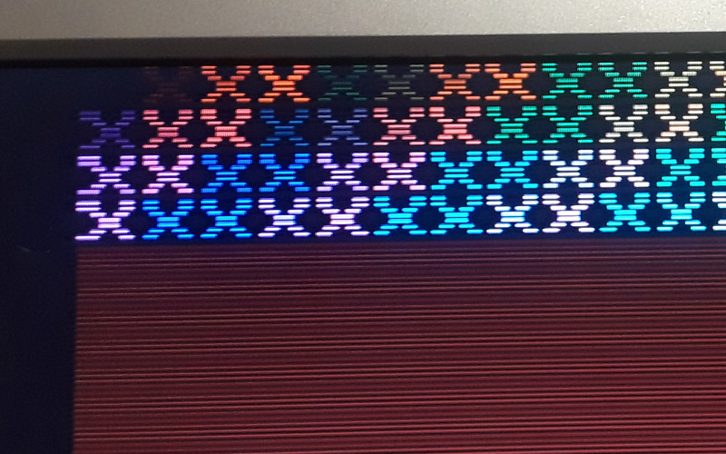
The "scanlines" effect is not a goofy attempt at mimicing a bad CRT monitor. The default video mode of the Cat644 is 256x240. This uses the 640x480 VGA timings, which means every line is doubled. Since this computer generates the screen using the CPU, over 90% of the CPU is taken up by this task. This is "slow" mode. If only every other line is drawn, you get the scanline effect, no loss in screen resolution, and 50% of the CPU is recovered. This is "fast" mode.
KittyOS
September 3, 2018
I am basing this around some previous work the first time I was writing software for this computer. I started making a framework called catos, but it didn't really work out. I never kept with the project. This time around, I am starting over, copy and pasting some of it into a new project called KittyOS.
So far, this is what is working: Read/write the serial port thru a chardevice structure.
Unix is based around the idea that everything is a file. Devices are just 'magic files' that when reading and writing causes I/O to happen. I am flipping this around: in KittyOS everything is a device. Part of this is the reason that perhaps I want to use KittyOS in other AVR projects. There may not be a filesystem available for use, and it doesn't make sense to emulate one just for the sake of being like Unix. Yes, there are many embedded Linux devices with no physical filesystem that run out of initrd or initramfs, but that is only because in Unix you need a filesystem because eveything is a file. The AVR has 4k of memory and 64k of flash, and I don't want to fill that up with a fake filesystem. In KittyOS, all you need are devices to read and write. There are a few different classes of devices:
Basic device: A basic device has one function: ioctl. Ioctl passes 2 integers to a device, a command number and a value. This might mean different things to different devices. For a serial port, it might set the baud rate. For a video card, it might change the video mode. Maybe this initalizes a SPI bus, or sets the mode on a temperature sensor from degrees F to degrees C, or maybe it changes the color of an RGB LED. It's just a basic command channel.
Char device: A character device supports everything a Basic device does, but supports serialized reading and writing. These might be 'files', serial ports, sockets, keyboards, mice, anything.
- read1: reads 1 byte from a device. Blocks until there is a character ready.
- write1: writes 1 byte to a device. Blocks if the device is busy.
- kbhit: returns true if a character is ready to be read. Name is taken from the dos conio 'kbhit' function to see if reading the keyboard would block
Block device: A device that reads or writes data in chunks, such as a disk. This is a little different from a linux block device. Linux block devices are still 'files' and can be read or written single bytes at a time, and the OS uses a block caching layer to actually read and writes blocks at a time. This is not supported in KittyOS. Reading or writing to a block device is done, in random access, one whole block at a time. This maps cleanly to the sdcard read and write sector commands, and probably most disk devices.
file device: A file on a disk (in a filesystem) is just a chardevice that supports two additional functions: seek and pos. This will reposition a read/write stream, or tell you where it is. The act of opening a file on a disk creates a file chardevice for the user to interact with. Instead of treating a virtual serial port as a file, KittyOS treats a file as a virtual serial port.
Selector device: A device that finds, lists, organizes or creates other devices. Supports the call 'subdev' which given a name and some flags, returns another device to use. It will also support another call 'list' which returns a list of available subdevice names. If opening a file on disk, it will create a chardevice that represents the contents of that file. On a disk a selector device might list other selector devices. (Hint: its a directory )
The SDCard filesystem will be organized like this:
- The SPI bus is a chardevice, since it reads and writes one byte at a time.
- The SPI bus will supports the calls IOCTLs lock and unlock, which prevent more than one driver from using the SPI bus at a time.
- The SD card block device will lock the SPI bus, and use it to read and write blocks from the sdcard.
- A filedevice driver will support reading and writing 'files' on the sdcard. A file is created by finding a free block. Files grow in a linked list fashion from free blocks. Existing files can opened by specifying their block number.
- A selector device will be created that lists other devices on the filesystem. This 'root list' will start at a known block number. This will list file devices by name (plain files), or will list other selector devices (directories)
The above seems like a lot of layers, but I still think the Atmega will mostly be held up waiting for data on the bus. I do have some sdcard routines that directly read/write spi, but I want to try making them go thru a chardevice wrapper, the same way serial routines currently do. Why? This is closer to how a modern OS might be structured. It's also very powerful to abstract things like this. If reading/writing SPI is done thru the chardevice, then what keeps me from simulating SPI devices in software, or debugging what is being sent to an SPI device by sending it over the serial port to my PC? Suppose by SPI bitrate is 2 MHz. Then on a 20Mhz atmega, there's 10 instructions per bit, so 80 per byte. 80 instructions is enough to traverse the chardevice struct pointer to the function that puts the next byte on the SPI bus
But, SPI isn't a regular chardevice is it? SPI doesn't read/write seperately like a serial port, but exchanges bytes: You always read and write at the same time. In the past I did do some experiments with treating the SPI as a serial port with only a read and write function. This was easy by keeping a 1 byte buffer:
- Write byte: Writes a byte to the SPI bus. The received byte is placed in the buffer. If there are multiple writes in a row, the buffer is replaced with the newly received byte.
- Read byte: If the buffer contains a byte, returns it without writing anything to the SPI bus. If there is another read, and the buffer does not contain data, a zero is written to the SPI bus, and the received byte is returned
This fits all the use cases of SPI I've come across so far. Either you write and then immeediately read, to do a byte exchange. Or you write several bytes in a row, ignoring the return value. Or you read several bytes in a row, outputting "don't care" values. This also maps well to how the AVR hardware works.
VGA Rewrite
September 6, 2018
I spent the last two evening rewriting the VGA driver. The VGA signal is bitbanged by the AVR, and all the details are here in this post 4! years ago.
I am rewriting the driver, because the old one stopped working. In the time since I last worked on the cat644, I switched from Atmel Studio 6 to Atmel Studio 7. My carefully ordered C code doesn't have the right timings anymore. C was never meant for cycle counting anyway. The new driver is in assembly. The old driver had the disadvantage of not being full width. I never managed to cram all 256 pixels in a scanline; the routine always needed to abort early. A compelte rewrite of the video interrupt was long overdue.
The original C code supported 2 video modes: slow and fast. Slow mode draws every scanline, line-doubling the framebuffer. Fast mode draws every other scanline, giving more CPU back to the user program. I'm doing the same thing here, except the video mode is changed via function pointer. The user can select which pointer is used for the video driver.
Currently there is no support for the keyboard. The first cat1 driver for the keyboard was interrupt driven. But, the interrupt conflicted with the video interupt, causing timing shifts an an unstable image when a key was pressed. The solution I ended up using was having the video interrupt poll the keyboard port every scanline, and if there was a change to the ps2clk pin, at the end of the scanline the input bit would be processed. This processing took too long, so there was no time to restore CPU state and return to the user program, so instead the interrupt handled the keyboard, waited until the next clock cycle, and then proceeded to draw the next scanline immediately. I can probably use that same approach here. However, now I will have gotten keyboard code in the video driver. I am considering adding a 'timer' interface, where there are multiple possible timer functions that can be called at different priority orders. When the interupt fires, the first thing that should be run is the horizontal sync code. Then, depending on if its vertical blanking, or a 'skippy' blank scanline, runs the keyboard function and returns to the user program. If it is a full scanline, draw the scanline, then call the keyboard function instead of returning to the user program.
Cycle Scavenging
September 11, 2018
10:15 pm
To output each pixel in the VGA routine takes two instructions:
	inc zh                     //incremenet address
	out io(RAMADDR_PORT), zh   //output new address
This is repeated many times as an unrolled loop:
	//define some macros

	.macro PX
		inc zh
		out io(RAMADDR_PORT), zh
	.endm

	.macro PX4
		PX
		PX
		PX
		PX
	.endm

	.macro PX16
		PX4
		PX4
		PX4
		PX4
	.endm


	//a bit later, when the time is right

	PX16
	PX16
	PX16
	...
	PX16  //256 pixels
The AVR has the feature that writing to the INPUT register of a port performs an XOR on that register and flips bits. If I already have the right value (the number 1) loaded, I can output 2 pixels using only 3 instructoins:
.macro PX2noppy_odd_even
	nop                       //do nothing!
	out io(RAMADDR_PIN), zl   //flip the last bit: the 0 on the address becomes a 1
	subi zh, -2  //skip 2     //count forward 2
	out io(RAMADDR_PORT) ,zh  //output the next even address
.endm
I replaced 16 pixels of the display with the 'noppy' version as a test. Everything works the same. This creates the same display, but every 4th instruction is a nop. What is the advantage? These nops can be replaced with any other single cycle instruction. So, one quarter of the 256 instructions used to generate the display (64 instructions) is potentially reclaimed. With caveats. I am limited to single cycle instructions (any 2-cycle one will break the timing), and there can be no jumps. Limited to basic arithmetic and bit operations: essentially branchless combinational logic. Not sure what I can put there yet.
On the original Hackaday.io project page for this, I had implemeneted a higher than possible horizontal resolution by making use of one of the AVR's PWM timers. PORTB is used for addressing memory. PORTB also has PWM pins, so I configured the PWM pin to toggle every cycle. With the code timed correctly, even though I could only increment and output once every 2 clock cycles, the PWM was making each 2-cycle long address break into 2 addresses. Similar to what I have tried above by flipping one bit without incrementing. Well, on the page I just linked to, I did realize even back then that if I used the PWM trick on a low resolution video mode, I only needed to increment and write once every 4 clock cycles. Leaving 2-cycle nops available. The idea back then was to implement an interpreter within those cycles. Now, that idea seems crazy, but I think if I can just reclaim enough CPU, I should be able to maybe process the PS2 keyboard within the nops recaptured from video. There are two problems with this 1)The way the PWM toggles bits complicates horizontal scrolling, since its not as simple as 'add one', the bit being toggles is actually bit number 3; very annoying. To make it work before I needed to write to memory in a strange swizzled order. And 2) If I were to implement hi-res video, the ps2 handling code will still have to go somewhere.
To get on with this project, I think I am just going to have the PS2 keyboard blank out a scanline for handling incoming bits. I can clean it up later.
VGA Bug
September 11, 2018
I messed up writing the VGA rotines the other day. I was wondering why the screen was vertically offset a little bit, despite the vertical blanking being the in the right spot. Turns out, it was not. I messed up my row counter. I never reset it! It would just overflow, so I was counting out 512 scanlines instead of 525. To save CPU time, I attempted to use two byte variables: one is the row to draw, and the other tracks odd vs even. This came out to less clocks wasted loading, incrementing, testing 16 bit values, etc. I would have to notch out pixels otherwise if I didn't do this optimization.
The real fix would be to use 16-bit math, but the longer loads, stores, and compares was blowing the length of the interrupt routine. I need the active video scanline case to be fast.
The trick was to keep the existing active video parts all the same. The interrupt routine is already abbreviated when there is a vertical blanking interval; it runs just enough to get the hsync/vsync timing right and then exits to the user application. So, in the vertical blanking interval, the rowcounter is hacked up to make the frame take 525 lines. The video driver still alternates odd/even for rows 0 to 254. (Scanlines 0 to 509). The next lines, the counters are locked to 'even' and 255. A seperate counter tracks how many scanlines beyond the counter limit, and when it equals 15, it then resets all counters to zero. (510 from 2x254, then + 15 = 525 lines). This works fine! This additional counter was then stored in the leftover bits of the odd/even flag. (Since it was a boolean, 7 other bits are wasted!)
Reducing display width?
Originally I rewrote the VGA routine to get better control over timing. Part of the goal was to optimize it so I can get the full 256 pixel width of the display. However, now there's extra stuff I haven't crammed in yet, like ps2 keyboard polling. If there is a change on the PS2CLK input, I suppose a scanline can be skipped, or notched out, without too much ill effect. But, another thing I wanted to do with this is support good horizontal scrolling. The VGA driver already support scrolling in both direction. However verical scrolling has something horizontal doesn't: a hidden area. Therea are 256 pages in a bank of memory, and vertical scrolling just changes which page is the first scanline, and there are only 240 visible lines. This gives 16 lines that can be written to in software BEFORE scrolling, and the user will not see the drawing. To do the same thing horizontally, there needs to be a strip of hidden pixels. If the width of the display is shrunk from 256 to 248 pixels, this gives a 8 pixel wide hidden area, and also provides 16 additional clock cycles to the video interrupt. If the text font used is 8 pixels wide, this gives a strange 31 character wide display. If the font is switched to an 6 pixel wide font, the display will be 41 characters wide.
Pin Change UnInterrupt
September 14, 2018
When I forst wrote the cat1 test program, I interfaced to the keyboard with an interrupt. The AVR had a pin change interrupt. When a key is pressed, the keyboard has a valid bit ready on the falling edge, so having the pin change interrupt make an effecient way to read the keyboard. There was a lot of fussing around getting it to work with the video interrupt. Ultimately, I ended up dropping the interrupt idea, and instead polled the keyboard port in software on every scanline.
My Hackaday.io post on my previous troubles with the Keyboard interruptToday, I was looking for a better way. I googled 'AVR pin change flag without interrupts,' and came across a few claims like this saying the AVR will still set the pin change interrupt FLAG even with that particular interrupt disabled. I tried it in Atmel Studio's simulator, and it seems to be correct.
I still need to check the flag... PCIFR, every scanline. But this is much less work than I had before. I added code to read the port, compare it to the last read (which means storing the last state in a variable), and the clock cycles were adding up. It was threatening some pixels int he display: I needed to blank out a few pixels to make space for this. With the flag, I don't think I have to. (I will probably end up blanking a few pixels: both to create an invisible draw space for horizontal smooth scrolling, and to give pixels to the sound output engine.)
The plan now is to check the flag at the beginning of the scanline... if it needs to be serviced, the scanline will not be drawn. If I get basic keyboard working along with this video driver, I will move on to the next thing: probably the SD card.
Keyboard Driver 'Done'
September 16, 2018
I think I have the assembly code all ready for polling the keyboard during the video interrupt. I need to solder up a new PS/2 connector and try it out. Hope fully tomorrow. (I stole the PS/2 breakout header I previously used in the project for something else last retrochallenge...) It's 'code complete', just untested. :-)
Keyboard and VGA working together AND a mystery!
September 19 2018
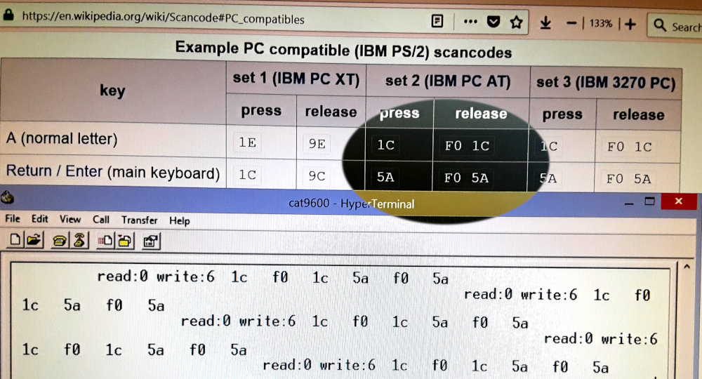
Here, a debug program is outputting the contents of the keyboard scan code buffer over the serial line. The read position is 0, and the write position is 6, meaning 6 codes are in the buffer, but none have been 'read' yet. Those bytes are: 1C (A), F0 1C (release A), 5A (enter), F0 5A (release enter). That's what I typed. And for a few days, that's what I would type, but not what would show up here!
I had VGA and video working together a few days ago. I took the 'cheat' route and just had a pin change event blank out an entire scanline. It worked perfectly. At a 30 Khz screen, if the keyboard is up to 15 khz, and the clock has a 50% duty cycle, the routine should be able to sample the bits just fine if it looks once per scanline. And it worked just fine.
I tried to handle the keypress without blanking out the screen. I did this on the original cat1 test program (years ago) when it was all in C:
- If this is a blank like, and pin clock changed, handle it and return to user program/
- If this is an active video scanline, and the pin clock changed, handle it AFTER the video, and then jump back into the next scanline handler. No return touser program, until there's either a blank line, or the keyboard clock is idle.
I thought I could do the same in this project.
It did not work in this case. Then I remembered that the sampling has to be at the same time every scanline. If sometimes I sample at the beginning (for a blank line), or at the end (for an active line), the important bit transition may have been missed. Basically if the ps2 pin clock is 50% duty cycle, if I don't sample evenly, something will be missed. So, instead I changed it to sample at the beginning of the scnaline cycle, at hsync, exactly at the same clock every scanline. This also didn't work! So I went back to the simple version that blanks out a scanline. (Thanks git!). And I ran by sample-and-save code immediately after my load-and-act code, and it still didn't work. Why the hell not? Well I have two versions of the sampling code here, both almost identical, and in the AVR simulator do the exact same time. One works, one does not! I even padded the working one with a NOP to make the io timings the same!
WORKING:
in zl, io(PCIFR)		//read pin change flags
andi zl, 1<<PCIF0		//isolate the flag we are looking for
nop				//skip a step to line up with not-working version

out io(PCIFR), zl 		//write the flag back.  If it was 0, this does nothing.  If this was 1, writing a 1 here clears the flag
in zh, io(KEY_PIN)		//read the ps2 port
andi zh, KEY_DATA | KEY_CLK	//isolate the clock and data bits  (bits 6 and 7)
or zh, zl			//add in the changed flag (bit 0)
out io(GPIOR0), zh		//store in GPIOR0, which is later read to get the captured ps/2 port snapshot, and the 'changed' flag
NOT WORKING:
in zl, io(PCIFR)		//read the pin change flags
sbi io(PCIFR),PCIF0		//read the flags, set bit 0, and write back
				//technically this might clear other flags, But no other flags in this register are being used, and should be zero
				//also, clearing an already clear flag should do anything.  It doesn't in the atmel simulator!
andi zl, 1<<PCIF0		//isolate the pin change flag
in zh, io(KEY_PIN)		//read ps2 port
andi zh, KEY_DATA | KEY_CLK	//isolate the clock and data bits
or zh, zl			//add in the changed flag
out io(GPIOR0), zh		//store in GPIOR0
Now if you look at the not-working version there is a slight race condition. It is possible that after reading the pin change flag, the change can occur right before the next instruction SBI, and I'll have a pin change state that I haven't captured. But, this race condition is only vulnerable for 2 instruction cycles (.1 us out of every scanline), and if every keypress is magically hitting this, despite me plugging the keyboard in at a random time, that is very very unlucky. Or the pin change circuit of the AVR has large delay in it between a pin change and the flag appearing. Or writing a 1 to a non-set pin change flag causes some errant behavior, maybe suppressing the next up-and-coming pin change? The simulator doesn't seem to have any odd behavior here. I can't make the simulator do the 'wrong' thing like that real hardware does. Of course, reality is correct, so the simulator is failing to account for something in the hardware. (Whether its a 'defect' in the hardware or not.)
I plan to apply this fix to the complicated version, and then move on to the SD card.
VGA Perfect
September 21, 2018
I took what I learned from the previous post, and applied to the the failed version of the VGA interrupt. Success! I now have a stable VGA signal, 248x240, with no pixels lost when typing on the keyboard. I'm keeping the simple version (which blanks out parts of scalines to handle keypresses) as a backup, and it is called VGA_NOTCHY. The version presented here is really hard to follow, so it's called VGA_SPAGHETTI. The pasta video driver supports both 'full' video mode, which draws every scanline, and 'skippy' mode which draws every other scanline.
In the halftime post, it was mentioned my explanations are text heavy. I agree. I've also spent a lot of time in the weeds of the video driver, so posting assembly code here will help no one. It's all in github if you want to see it. So here's a flowchart of the VGA/PS2 interrupt routine. The red line shows a typical path if there is activity on the PS/2 bus during/between active scanlines. There are shortcuts thru the maze if the keypress is handled during a blank scanline. Maybe I took the TRON LightCycles maze too literally when designing this video driver.
Some important paths to look at: (These cases all seem to work)
- Keypress detected during active video scanline, and the next scanline is also active. path shown in red below
- The first time thru the loop saves machine state, including memory bus status
- The second pass doesn't save state, but outputs scanline, then restores state and returns.
- If another bit of bus activity has occured, this could also just keep doing multiple scanlines in a row, witholding cycles from the main program until either the keyboard has stopped sending bits or there is a blank line.
- Keypress detected during active video scanline, and next scanline is blank. (Either for vertical blanking, or 'skippy' video mode.)
- The first time thru the loop saves machine state, including memory bus status
- The second pass skips all active video, but restores memory bus state, and returns to user program.
- Keypress detected during blank scanline (Either vertical blanking or 'skippy' mode.)
- Machine state (cpu) saved, but not memory bus state.
- After bits are handled, the cpu returns to the user program, without touching the memory bus
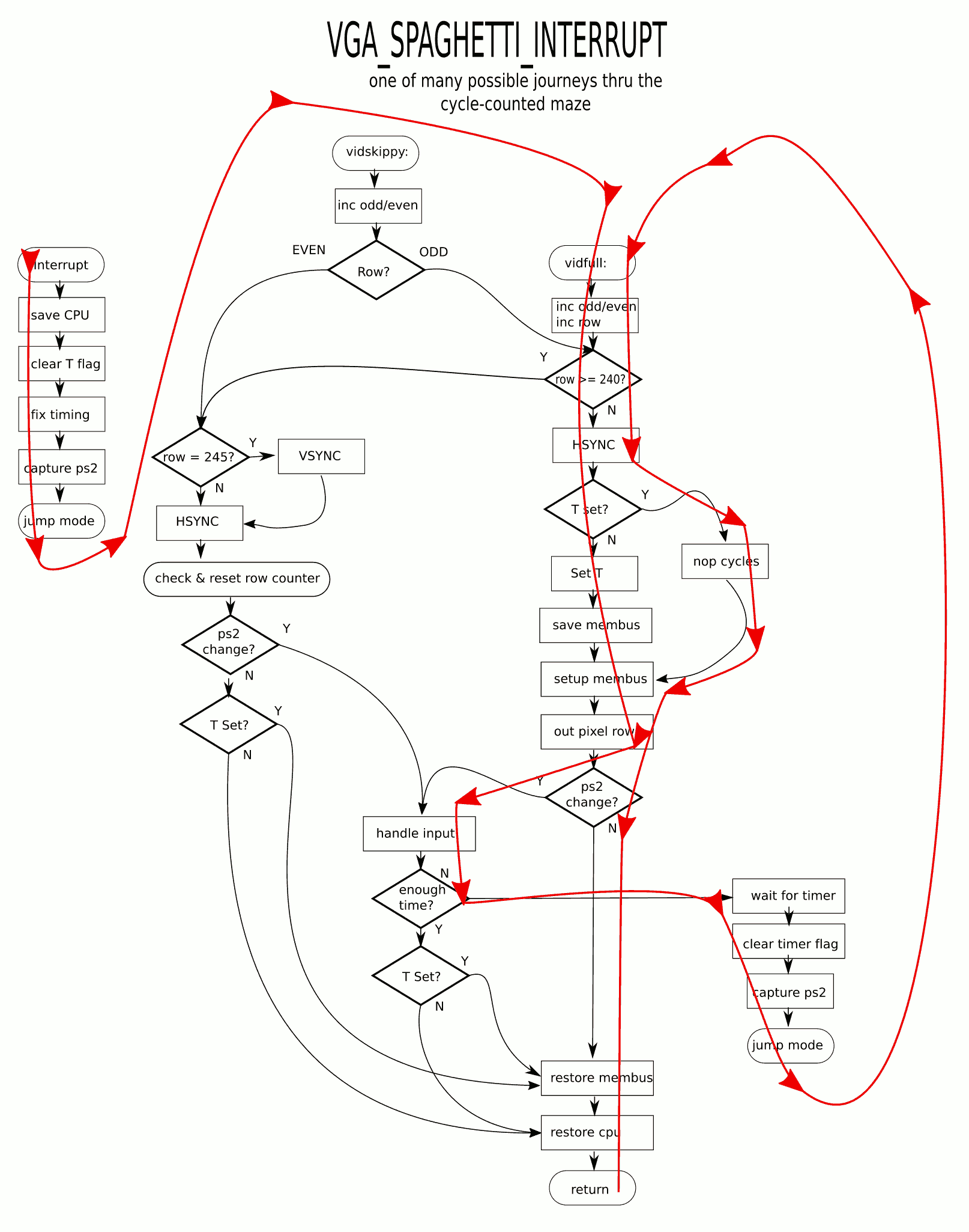
(Clicking makes it bigger, but not less messy)
SD Card Initialized
I took my old 'raw' sdcard driver which manipulated SPI directly, and ported it to kittyOS. All the reads and writes to the SPI port is now done thru the SPI chardevice. So far, the SD card be be initialized and the capacity read. Which means, commands can be send to, and replies recieved from, the SDcard. The existing sector read/write code should also still work, so I will stop for now
The plan to finish off the retrochallenge is to add the bytecode interpreter. I have one that I've developed in simavr over a year ago. I'm going to add this to the kittyOS project. The plan is for the computer to read the first sector off the SDCard, and run it in the bytecode interpreter. Then, it's 'done', in the sense that the user can put programs on the sdcard and run them in some fashion. There are many syscalls that need to be made from the interpreter, but for the retrochallenge, there are only a few critically needed to make this a 'computer' that can do 'useful' work:
- Read char (keyboard, serial port)
- Write char (VGA console character writer, serial port)
- Read block (sdcard)
- Write block (sdcard)
- Copy internal SRAM to XRAM (use external ram as storage, OR draw to screen)
- Copy XRAM to SRAM (get things that were stored in XRAM
- Poke & Peek: read and write AVR physical addresses (not virtual machine heap): Can change video modes, mess with I/O ports, etc
The above would create a minimal, bootable system that can control the hardware. Now, the question is, for reading/writing files on the memory card, and dealing with dynamic memory allocation, and things like that, should that be written in C and exposed as high-level syscalls? Yes, I want file and memory management to be done in C, where it is compiled to AVR code and as effecient as possible. But for the retrochallenge goal, having a minimal BIOS-like environment that reads raw sectors I think is a more appropriate goal. As long as the system can boot and run a user-provided program on SDcard that can control most of the hardware, its a 'computer'. No reason why the SD card program can't be a shell, or assembler, or bootloader, or whatever. Even a full CP/M or DOS like environment could be made inside the VM with raw sector commands. But, I will stop short of that. The minute a program needs to do more than load itself from the sdcard, it will be time to implement the high-level calls that split the sdcard block device into multiple char devices.
VM Interpreter and Syscalls

I took a VM interpreter I wrote a couple years ago as a proof of concept, and integrated it into the OS. I exposed a syscall interface that calls into C with 3 parameters: an 8-bit syscall number, and two 16-bit values. The syscall can also return a 16-bit value. I haven't implemented much in the way of syscalls, other than printing out that the VM requested a syscall.
I also created the first system 'mux' device, which allows the listing and finding of other devices. There is now a mux named mainmux that lists all the current devices. This is the current kittyOS boot process:
- Chip45 boot loader runs and timeouts, jumps to the AVR application section (contains kittyOS)
- main() of the application section is where kittyOS starts. The first thing it does it print 'kernel start' to the system dmesg_dev, which isn't pointing anywhere yet. This was a test to see the writing to an unitialized device doesn't do anything bad.
- The serial port (ser0) is initialized, and the dmesg device now points to it. All debugging messages after this are sent to the serial port
- External RAM and VGA interrupt is initialized. This brings the screen and keyboard to live
- dmesg is changed to point to the 'scr' device, which is a virtual console that draws characters on the VGA screen. The scr device is found using findDevice, which uses the mainmux device.
- As a test, all the devices in mainmux are enumerated, and their type is displayed on the screen.
- The system now transfers control over to the virtual machine interpreter. There is a short test program stored in a char array 'introm.c' This program just adds a couple numbers to test the VM is alive, then does a couple syscalls. It then ends in a halt loop.
This is what I want to do to finish off the retrochallenge:
Minimum syscalls to create small interactive program in the VM- FIND_DEV: return device handle by name, such as 'scr' or 'ser0'
- WRITE_CHAR
- READ_CHAR
- HEAP_INFO: return address and bytecount of unused memory
How am I doing on memory? Just a little over 8k of flash is used, and I can use up to 60k without having to find a smaller bootloader. There is plenty of program space free. On RAM? So far, I get to give the VM over 2k, and there's still unused space. One thing I can do in the future is reposition the stack. Once I enter the VM interpreter, there is no reason to ever come back, except for an interrupt or a syscall. These go 'deeper' in the stack, and don't backtrack. The interpreter should be able to carefully move the stack back to the end of RAM, overwriting the stack frame for main(), which will never be needed again.
Some more documentation, maybe even a video
Done(ish)!
September 30 2pm Pacific Time
Kitty OS boots, and outputs on the serial line:

Then switches to the VGA driver, and runs a short program:

I have gotten an interpreted program to find the screen and keyboard in the system main device mux. The program only prints "Hello World", and then enters a loop repeated reading the keyboard and writing the characters to the display. It is the minimal interactive interpreted program sample. It demonstrates the mux device, the chardevices, and interaction between an interpreted program, the interpreter written in assembly, the VGA driver interrupt, the PS2 polling algorithm, and syscalls written in C. Without crashing.
Github Repo
This is the interpreted bytecode program:
test.sldi a @out_dev offset syscall 1 #find device swp b #b has the device ldi a @hello offset nextchar: ldc a #get character *a to c swp c # c has ptr, a has char #jump to halt if low byte of A is zero ldi d $00ff and d jaz @done syscall 2 #write reg A to device in B swp c #get pointer ldi d 1 add d jmpr @nextchar done: # register B has output device swp B # A has output swp D # D has output device ldi a @in_dev offset syscall 1 #get input device swp b # b as input device again: syscall 3 # read a char #char in a , input in B, output in D swp b #char in b, input in A, output in D swp d #char in b, input in D, output in A swp b #char in A, input in D, output in B syscall 2 #write char #zero in A, input in D, output in B swp b swp d swp b jmpr @again halt: jmpr @halt out_dev: string 'scr byte 0 in_dev: string 'key byte 0 string ' hello: string 'Hello World byte 0
And no, this is not running off the SD Card. I didn't get that far. The interpreted program is stored in the AVR Flash, and copied to SRAM, and runs out of SRAM. It is stored in a file called "introm.c". Future versions will find the sdcard in the device list, read the first block, and then run from there. But not yet. Maybe in the next retrochallenge, I will make a game for this computer!
And sometimes it doesn't go to plan! This was a bug I had this morning.

Begin Again
March 1, 2019
This time for the retrochallenge I am going to continue to write KittyOS. This is where I left off:
- Hierarchial device driver structure
- Working hardware drivers for keyboard, VGA, external memory, serial, spi, sdcard
- 16-bit bytecode interpreter
- Syscall support with some syscalls working
This is what I'm planning for KittyOS (in general) :
- Develop a simple filesystem for the sdcard. (I am also considering alternatives to the traditional filesytem.)
- Integrate a memory allocator, which allocates both internal SRAM and external SRAM
- Finish implementation of enough syscalls to load and run programs from the sdcard, and read/write to the sdcard filesystem.
- Add sound support: The hardware supports it; just need to find more time in the video interrupt to make it work.
How much will I get done in the retrochallenge? Who knows. But I think the first thing to mess around with is dynamic memory allocation.
Setup Environment; Design Memory Management
First week, March 2019
Since the last retrochallenge, I built a new Windows computer, and I had not yet set up any AVR workflow on it. So I spent some time getting Atmel Studio installed, along with a bootloader I like to use... Chip45. I prefer RAW AVR programming to using Arduino. I really like usign AVRDude when I'm using blank new chips. But, if I can spare the flash space for it, I will put on Chip45, because then I can reprogram over the serial port, instead of ISP.
I was able to build the previous retrochallenge's KittyOS code, and flash it with Chip45. To make sure all the files I needed were really in github, I set up the new environment using only files I uploaded there.
I might not do much more this week, but I should at least write up how I imagine memory management to work on this computer
Internal SRAM
Avr-gcc's clib provides a simple malloc. I intend to NOT use that at all, and instead write my own. For a previous AVR project I was goofing around with, I wrote a basic allocator, and I intend to use parts of that here. (Or perhaps rewrite it from scratch.) The Atmega 644 contains 4KB of SRAM. One possible upgrade path for this computer is moving at an Atmega1284, which has 16KB of SRAM. I want any solution here to be able to address up to 16KB of internal SRAM. I am also only going to allow allocations up to 512 bytes. The intention is the SRAM will be used more as a cache for programs running in the VM interpreter, and less for actual data storage.
/* Each block of memory allocated begins with a 2-byte header.
   This header supports tracking free blocks and reference
   counting
*/

#define MASK_FLAGS	0xC000
#define FLAG_FREE	0x8000  /* 1000 0000 0000 0000 */
#define FLAG_HANDLE	0x4000  /* 0100 0000 0000 0000 */
#define MASK_SIZEW	0x01FF  /* 0000 0001 1111 1111 */
#define MASK_REF	0x3E00  /* 0011 1110 0000 0000 */
#define REF_INC		0x0200  /* 0000 0010 0000 0000 */

typedef u16 mheader_t;
- void* mmalloc(int bytes) //allocate between 0 and 512 bytes
- void* mmaddref(void*) //inc ref count and return the pointer. Return NULL if inc fails (if counter is saturated)
- void mmfree(void*) //dec ref count, free when reaches 0
There is also the above-mentioned 'handle.' Some regions of memory will be associated with a 'handle'. If the handle flag is set, the 1st word of the block following the header will be handle number.
External SRAM (XRAM)
The CAT-644 has 128K of external SRAM. 64K of this SRAM is devoted to graphics. It is possible to come up with video modes that take less memory (If you don't want wrap-around scrolling, the display only takes 60K of memory), but for now there is no need to work out schemes to expand memory usage. The other 64K will be used for data. The external memory is not directly usable by th CPU, but must be bitbanged in software. Experiments writing to memory shows this is not that slow, but is slower than internal SRAM. XRAM will be used for the bulk of data (and code) storage for the CAT-644
The plan for XRAM is that each block of XRAM will be associated with a handle. Allocating a block of XRAM does not return a direct pointer to it, but returns a handle. For now the implementation of the handle WILL simply be the address in XRAM... so it is a pointer. But it is not a pointer that can be used directly by the AVR... the contents of XRAM need to be read or written programatically. This is where the handles come in. A program needing to read or write a structure pointed to by a handle, will have to call a function. If that structure is already on the SRAM heap, the reference count will be increased. If it is not, then the object will be retrieved from XRAM and put into SRAM.
These are the planned XRAM functions
- handle_t halloc(int bytes) //allocate between 0 and 512 bytes, get a handle
- void* hgrab(handle_t); //retrieves object by handle, returns pointer to it
- handle_t hrelease(handle_t) //releases the 'hold' on a handle. Object is not updated in XRAM (for objects that were only read)
- handle_t hupdate(handle_t) //releases the 'hold' on a handle. Object is written back to XRAM.
SRAM Mini-Malloc
March 15, 2019
I implemented and tested mmalloc, mmfree, and mmaddref in Linux using gcc. I used unsigned int 16 (u_int16_t) and void* for all the data types. It SHOULD run the same on both x86 and avr. There are no void*'s actually stored in the heap at all... the only way to find things in the heap is to walk it. Theoretically you could have up to a size_t heap, and this would still work, as long as each data block is 512 bytes or less.
March 16, 2019
Mini-malloc ported easily to the AVR. It has a 2K heap, and there is plently of data space left for other things. I would be happy with a 3K user heap on a 4k machine.
Next is to write the XRAM alloc functions, which will be along the same lines as this. For now, in XRAM, to get going in other parts of the projects, XRAM will have a stub that allocates only and never frees.
Non-paged Virtual Memory
The intended use of handles is to create a sort of Virtual Memory type arragement. But it is not 'paged' virtual memory as modern CPUs would use. The user programs will ONLY allocate thru the use of handles. The program will ask for access to a handle, get a pointer, modify the data at the pointer, and then release the handle. The program should not keep many handles 'open' at a time, just whatever the current working set is. The simple, initial implemention will do a lot of copying back and forth from XRAM. But... just because a handle is released does not mean it has to be copied back immediately. When the last 'holder' of a handle releases it, the item can instead of being mmfree'd, be put in a queue. Only when mmalloc is about to fail, does it really have to copy the object back to XRAM. This resembles swapping on demand in a paged memory system.
XRAM Mini-Malloc
March 17, 2019
I copy/pasted my mminit and mmdump functions to work with external ram instead of using sram. I was able to initialize, and dump the blocks of the memory headers. Getting xalloc and xfree working should also be just as easy. I even did a quick test where I inited the VRAM section as the heap, and saw the memory arena paint on the screen.
The next thing to implement after that is halloc, haddref and hfree. What do those do? Those access memory thru handles. For now, the HANDLE will actually by the xram address. This does not have to be the case in the future; just will be for the moment because it is convenient, and makes it so I don't need to implement a handle table.
This is some basic pseudocode to grab and release items by handle. The idea is that a structure, such as linked list, will use handles instead of pointers.
 handle_t halloc(uint16 bytes) {

	xptr xp = xalloc(bytes);   //allocate external memory

	return xp;		  //return external pointer AS handle

 }

void* hgrab(handle_t h){

	void* p = findInHeap(h);  //see if item already in heap

	if (p)
		return mmaddref(p); //attempt to increase heap's copy ref count, and return it

	//not in heap?

	size = getObjectSize(h)
	p = mmalloc(size); //try to allocate memory in heap for object

	if (p){
		memcpyx2i(p, h, size); //copy to internal memory
	}

	return p;  //return object OR null
}

void hrelease(handle_t h) {
	void* p = findInHeap(h);

	assert (p not null) ; //releasing something we don't have?

	if (mmrefcount(p) == 1) { //if this is last reference to it
		memcpyi2x(h, p, getObjectSize(h)); //copy back to xram
	}

	mmfree(p); //decrement ref count, free from heap if gone

}


example usage: (ignoring error conditions)

struct listnode{
	handle_t string;
	handle_t next;
}

printStringList(handle_t list){

	while(list){

		listnode* plist = hgrab(list);   //get listnode struct
		handle_t next = list->next;      //next next handle
		char* str = hgrab(list->string); //get string
		prints(str);                     //print it
		hrelease(list->string);          //release string
		hrelease(list);                  //release list
		list=next;                       //continue at next handle
	}

}
While it seems cumbersome in C, I want to make it so when a programming is running in the virtual machine interpreter, this is all taken automatically. All objects will be referenced by handle instead of pointers. Since the interpreter runs out of SRAM, and not XRAM, it will even be necessary to split the program code into multiple handles and jump or call instructions will need to grab and release code handles. When it works how I imagine it to, the running program in the VM will behave like it has a full 64K of RAM. I don't want to get too far ahead in my thinking, but there is no reason why, if a handle table is implemented (instead of using the physical XRAM addresses) handles can't be swapped to and from disk or even requested over the network. Currently all handles will be xram word addresses, and take the form of 32768-65535. (Words 0 to 32767 make up the video ram). Handle space 0-32767 could be trapped to a callback were requesting a handle's contents are fulfilled by any function. I'm not sure what to use it for, but it seems like it could be powerful.
XRAM Mini-Malloc Continued
March 19, 2019
This morning I ported mmalloc to XRAM. It was fairly easy. In mmalloc, I used u16's as the base data type. The memory block header is a 16 bit word, sizes are counted in words, everything is word aligned. In XRAM, I decided to address everything by word address. The functions xpeek and xpoke (which I still need to optimize... they use the memcpyix2 and memcpyx2i functions I previously wrote) read and write words at word addresses. It make it very convenient to replace all void*, with just u16's, and every *ptr = foo to xpoke(ptr,foo).
I initialized the heap in the top 64k of ram (away from video memory), and did a few allocations. One that creates a remainder block, and one the requires combining the remainder with a full block and creating another remainder block. After dumping the heap, everything looks as expected. I seem to be able to allocate memory in external SRAM just fine.
Next steps:
- Implement halloc, hgrab, hrelease
- Add handle-awareness to interpreter (maybe just as syscalls?) for DATA
- Add handle-awareness to interpreter for CODE (call-by-handle, jump-by-handle)
- Add read/write block device syscalls to interpreter (block devices drivers were working in last retrochallenge, just not bound to the interpreter syscall list)
- Automatically read 'boot block' off of sdcard at boot and execute it
If I complete the above steps, I will have a minimally functioning system that can read VM instructions from sdcard, and run a program with minimum functionality to: read keyboard, write display, use serial port, read/write sdcard (no filesystem, just raw blocks), and allocate its own memory dynamically
SRAM/XRAM Swapping Working
March 20, 2019
A basic implemention of halloc, hgrab, and hrelease is working! I was able to allocate external memory, put data in it, then recall it later by handle. The system now has 2K of SRAM user heap 'cache', and 64k of XRAM.
	/* This is a basic test of halloc, and handle-based SRAM swapping /*

	char* s = "This is a string";

	char * hp;
	char * hp2;

	//allocate memory, create a handle for it
	u16 h = halloc(strlen(s)+1);


	/* HP and HP2 should be the same pointer */
	hp = hgrab(h);
	hp2 = hgrab(h); //get again

	DMESGF("%x %x\r\n", hp, hp2);

	strcpy(hp, s);  //copy it

	/* release both grabs on the item */
	hrelease(hp);  /* should dev ref count in sram */
	hrelease(hp2); /* should copy & destroy the buffer */

	char* other = mmalloc(10);  /* allocate memory.  Should 'steal' the pointer that was released above */

	DMESGF("%p\r\n",other);

	hp = hgrab(h); /* Grab the string by handle */
	DMESGF("%p %s\r\n",hp); /* Should print 'This is a test', and it should be at a different physical address than before.  */
And debug output of the allocator is doing what I expect:
OUTPUT                                    Meaning
-------------------------------------------------------------------------------------------------------------
new handle 8001                           created object
8001 not found in heap                    first grab: object not in internal heap yet
xobject size 18
copy from x                               copy from external memory (is uninitialized garbage)
8001 found in heap                        second grab: object still in heap, just add to refcount
hp 0xb52  hp2 0xb52                       shows both grabbed pointers are same physical address
found handle 8001                         first release
found handle 8001                         second release
last reference, copy to x                 the second release trigger writing to external memory
other 0xb52                               a different malloc took our old physical address (b52 above)
8001 not found in heap                    grab the object
xobject size 18
copy from x                               swap into internal ram
hp b5e This is a string                   string still intact; at a different physical address
There are a lot of optimizations that can be done in the future. The last release doesn't have to trigger a copy to external ram; not until another mmalloc needs memory. If an object is only read and not modified, there does not need to be a copyback. Perhaps a mmalloc can succeed, but if a released object is moved instead of copied back. There are a bunch of scenarios, but I am not going to implemenet any of them until actually needed. I just need to keep them in mind so I don't take the design somwhere where the optimizations become impossible.