Retrochallenge 2018/04
(Retrochallenge main contest page.)What will it be this year? I have an Atari 5200, but its joystick is terrible. I have 4, but they are all broken. I have 2 that are broken in different ways, so I should be able to make 1 working salvage one, but that's no good. I will try to make a new one from arcade parts!
Monday April 30, 2018
Almost
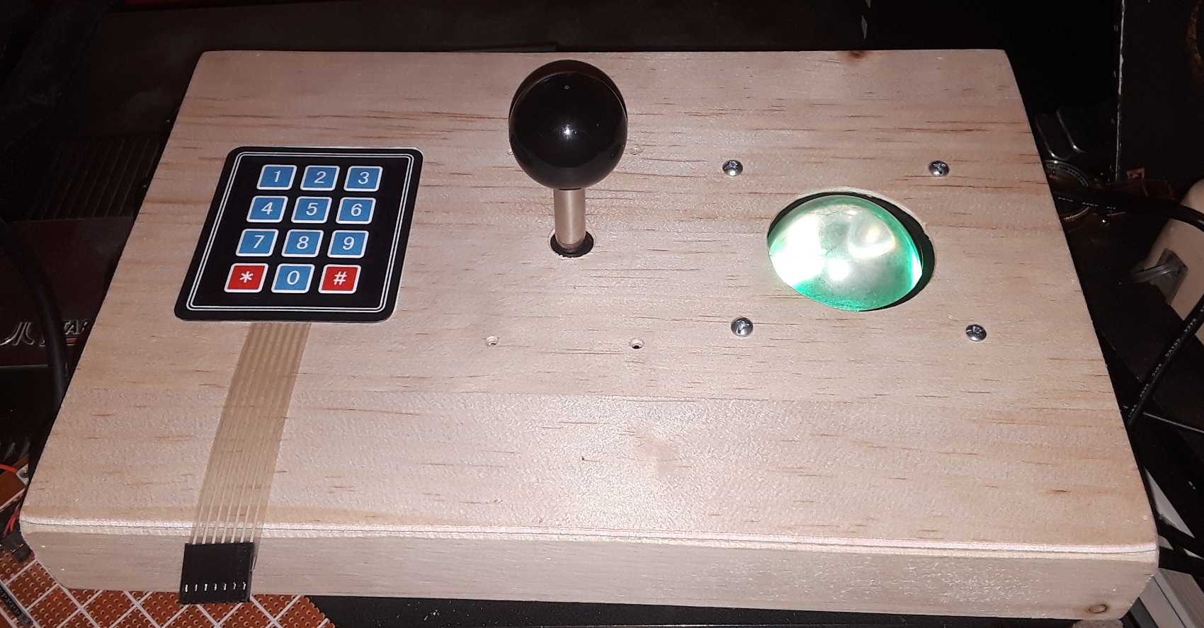
I almost got it done, but simply ran out of time. I will finish this project soon, post the code, schematics, etc. What works so far, is the trackball moves the cursor smoothly in Centipede, and the boxing is figured out. There will be a DPDT switch to swap between the trackball controller and the 8-way joystick. The wiring is figured out for the joystick, and I tested it with aligator clips, but needs to be soldered. The buttons and the keypad is not hooked up yet, but hese are purely a soldering exercise. At least now you have an idea of what it will be when its done.
Sunday April 29, 2018
It's nearing the send, so I should write up what I've done so far. I've installed arcade switches on a box, and soldered the trackball adapter onto a permanent circuit board. I spent the last week or so heavily tweaking the software. I ended up removing the transistors from the trackball pwm circuit. The AVR now directly drives PWM into the 5200 joystick port thru a resistor, instead of switching power provided by the pot-common pin. Why? I had a lot of trouble getting the PWM to work from one day to the next. The center seemed to... well drift. If I just wanted center + hard left + hard right, it would have been fairly easy, but I wanted to have 2 cursor movement speeds. The Centipede cartridge directly supports slow cursor movement when using the joystick, and when the trackball is moving slowly I wanted more continuous pulses of slow movement, instead of narrow pulses of fast movement. Instead of moving the cursor 4 pixels every other frame, its better to move 2 each frame, right? Well, it turns out that games using the 5200 trackball such as Centipede can actually self-calibrate. It turns the pot-common voltage signal off. The official Trakball controller sees this, and disables trackball motion, while still outputting the center voltage. This is different from the passive joystick, which outputs nothing when the pin drops out. I found that if I continuously output the center voltage even the pot common drops out, I get a more consistent center, and PWM is much easier to tweak. Since I no longer am using pot-common as a current source for the pot signal, there's no need for the transistor. Removing the transistor also made the PWM values more linear. My guess is that Centipede drops the pot-voltage pin at startup to 1) detect center and calibrate and 2) test to see if the controller present is the trackball. When I wire up a passive pot for cursor control, and I move it slightly from center, the 5200 does not calibrate the center. The game must be detecting a trackball is present and doing something differently. This also explains why some games don't work very well or all with the official trackball.
What is left for tomorrow? I'll post some more pictures. I also need to mount the circuit board, trackball, and arcade stick into a box. I have the box already... and I already have tested the 8-way joystick (for Pacman, etc ) circuit. I just need to drill some holes and solder a couple connectors. After work, before midnight.
Monday April 16, 2018
It basically works
I just needs a circuit board, a nice box, and everything else mounted
Saturday April 14, 2018
I got PWM working on one channel. I integrate the trackball delta so I have position value from 0 to 255. I then feed this value into the PWM register. This lets me use the trackball as a slider from 0 to 100% duty cycle. The current PWM value is also printed out over the serial port. This is so I can test which PWM values correspond to different speeds of the joystick. Note, this is NOT the intended operation of a trackball controller. This is just a test so I can input different PWM values and see what joystick setting this corresponds to. Under normal operation, this should be self-centering.
I determined PWM values for CENTER, the slowest LEFT speed, and the slowest RIGHT speed. I then modified the program to always output the center PWM position, until either the trackball is moved left or right. The result is I can recisely move the player left or right in very small trackball movements, way more precise than if I had the regulat 5200 joystick. Moving the trackball faster does NOT result in moving the player faster; for that I need to output a more extreme PWM signal. I need to sit down and make a table of different PWMs for joystick speeds. Playing with the joystick on Centipede, it seems there are only 2 or 3 actual speeds the player can move at. I think I can simulate any speed I want by rapidly swithcing between fast and slow.
I got serial input working. Serial receive is more sensitive to timing than sending. When I update the output ports when sending only once per bit, everything is fine. But when receiving, I need to sample the port more often. Why? When the timmer interrupt fires, and it notices the input port is LOW, that is the start bit. But did it catch the very beginning of the start bit, the middle, or the end? If the sample is too close to the edge, and the wiring isn't perfect (I'm on a breadboard right now), then I may be between bits. The solution is to sample the port more often. This is probably overkill, but the port is now sampled at 8x the baud rate. When the start bit is samples, a flag is set so that the next 4 interrupts (1/2 of a bit's worth of time) is used to wait, and then the bits are sampled at 8 cycle intervals. This puts the sampling directly in the middle of the bit's time range. This seems to work just fine.
Friday April 13, 2018
Morning
Mouse PS/2
This morning before heading to the office for my day job, I changed the keyboard LED command to the command for the mouse to start sending data. After plugging in the trackball, and moving it around, I seem to be recieving trackball motion data. I'm halfway there! I just need these values to correspond into PWMs for the joystick
Evening
Serial input, sortof.
I tried adding serial input, because I would like to send commands for testing from a PC. I am going to add PWM soon, and I want to specify different duty cycles to test. I sort of got it working, but I get some garbage characters. I'll spend a little more time on it, but I may give up and use a POT and analog input on the AVR as an input variable for testing PWM. What I need to find is the 'center' PWM, where the Atari thinks there is a 250k pot there. Then if I get a 'left' mouse movement or a 'right' mouse movement, the PWM duty cycle will decrease or increase momentarily, proportionally to the ball speed. When the ball stops moving, the PWM should return to the center duty cycle. This should approximate the function of the 5200 Trackball.
Thursday April 12, 2018
Full Duplex PS/2
Ok, after deglecting this project for a week, I sat down for a few hours and got things going. What do I have now? I made 2 major changes:
- Timer interrupt driven serial Instead of busy-waiting on the timer when waiting between bits, the serial sending code is in a timer interrupt. Whenever it's been long enough between bits, the interrupt routine runs. It finds where it left off, send the next bit, if any. The 'serout' function, which previously sent a byte by waiting for each bit, just busy-waits for the serial interrupt to have finished the previous byte, and then inserts the next byte in the buffer. Wait, wasn't the point to get rid of busy-waiting? No, it was to make timing serial easier. The serial out function allows you to specify a function to call while busy-waiting. In this case the 'idlefunc' is the ps2 polling loop. What this does in effect, is actively watch the PS/2 port in a tight loop, and occasionally feeds a byte to the serial interrupt as needed.
- Host-to-device Communication When using a ps/2 mouse, the mouse needs to be told when to start sending data. This means the host needs to send a command to the device, which is something I never implemented. I tested this by sending a command to turn on a LED on the keyboard. This took a while to get working, but now that I can send a command to a keyboard, I should be able to just replace the 'turn led on' command with 'start sending data.' All the rest of the code should work fine. The mouse should start sending status updates, and they will fill my already implemnted 'keyboard buffer.' Lets try that tomorrow.
Thursday April 5, 2018
Dev Workflow
I took one of my ATTiny84's and set it up on a breadboard. When I am programming AVR's and they don't already have a bootloader, I use 'dumb' parallel port programmer off of my old K6-2 computer running Ubuntu 10. When developing for AVRs, I usually code in Atmel Studio. I copy the .hex files to the Ubuntu machine, and I upload with AVR Dude. This sounds cumbersome, but once all the windows are open, it's quite easy. I hit build, then click and drag the .hex file to the Ubuntu machine using WinSCP, and then in a putty window, I press the 'up' arrow to run the AVRDude command again from the shell history. The parallel port is wired up to the breadboard, and the AVR is programmed in-circuit.
The first thing I did was blink an LED to make sure the ATTiny was hooked up to the PC correctly, and was alive. After that, I need to write on a serial port, so that I can get some debugging information. It turns out, I forgot about this: ATTiny's don't have serial ports. But, due to a previous retrochallenge project, I had ended up writing a software inplementation of RS-232 for the COSMAC assembly, so rewriting it in C on an AVR didn't take long. I only implemented 'send,' as I don't need to read anything from the PC. Once I got 'Hello World' working over the serial port, it was time to read the PS/2. (I could have used an Atmega 328 instead, as I have a couple, or even a full Arduino, but where's the fun in making it easy?)
Reading a PS/2 mouse is a little more complicated than a keyboard, because you need to tell the mouse to start sending data. Most keyboard auto-initialize. I had previously written a PS/2 keyboard reader for another project, so I just pasted that code into here. The other implementation was interrupt-driven, but I am using tight loops busy-waiting on timers to implement serial send. So, I switched the PS/2 code to poll. The CPU continuously pools PS/2, and when a key is available, it sends a debug message over the serial port. There is one pitfall to this: In multi-byte PS/2 packets, the time taken to send the status over the serial port to the PC obscures the time spent reading the other bytes in the packet... meaning it only displays that 1st byte of each packet. That is fine for now, as I am just checking I can read from PS/2. Also, when this is all hooked up an an Atari, there's no serial port involved at all... just changing a PWM register.
The next step is to send a command from the AVR to the keyboard. I will just try to blink a light on the keyboard. Once I can do that, I can switch the command to the mouse command to start sending data. Then I can plug in the trackball, and see if I get updates from the mouse. The mouse sends 3 bytes at a time, so I probably want to buffer 3 bytes before sending over serial.
I am also considering changing the serial transmit routine to be timer-interrupt driven. Then the program can poll the PS/2 port in a tight loop, and the timer interrupt will fire periodically when it is time to send a bit over RS-232. Wait, didn't I just say I won't need serial in the final version? There is also another motive to this project: The serial baud rate I have chosen is 1200. That is the baud rate of a serial mouse. One of the machines on my KVM is super annoying: It only accepts a serial mouse, but everything else accepts PS/2 or USB. If I can make an active PS/2 to serial mouse converter then I can ditch the terrible serial mouse that is used only by that one computer. Good thing I have two ATTiny84's.
Monday April 2, 2018
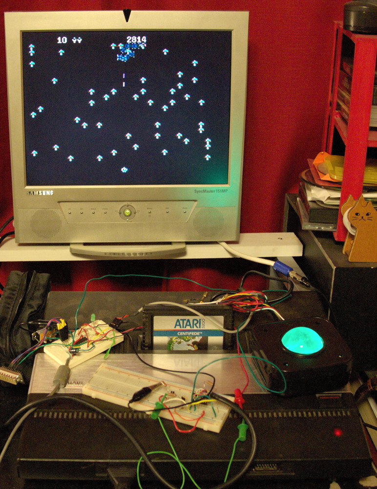
I took one of my dead controllers, cut the cable off, and wired it to a header. On this breadboard I have a resistor between the ROW and COL keypad pins, which similates holding the start button down. This makes the game immediately start. Also, whenever the game is over, it will immediately restart. This to is to make testing easier. The game I'm using to test is Centipede, since the player cursor can be freely moved, and with a trackball, should behave like a mouse cursor.
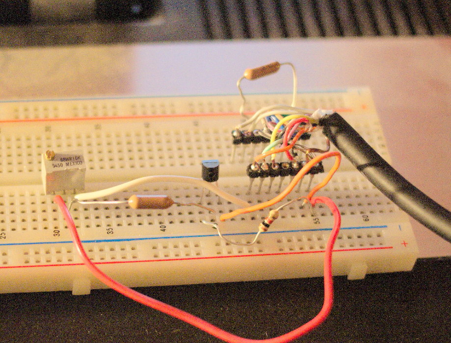
The player 'magic wand', as it is called in Centipede, is controlled by an analog joystick. Each axis has a 500k-Ohm potentiometer. (I will draw up a schematic soon to make this description easier.) A capacitor inside the Atari is charged up through the potentiometer and eventually the capacitor reaches a high enough voltage to register as high logic level. The time taken to charge the capacitor is dependant on the current flowing through the pot, and the Atari simply measures this time. This is exactly how old PC game port joysticks work. On this breadboard, I have replaced the pot with a transistor. When the transistor is off, it is high impedance is doesn't allow current to flow. The Atari sees this is the joystick being all the way to the right. When the transistor is turned on, the transistor acts as a short. I have a small current limiting resistor (1k) for protection. The Atari sees this as the joystick all the way to the left. The base of the transistor is connected to a pot, in this case a 1k pot, which lets me set the base voltage of the transistor, and set the operating point somewhere between off and on. I can precisely control the speed of the player cursor andwhere from full speed left, stopped, and full speed right thru this pot. This is simply a test to see if I can isolate the resistance of the transistor the Atari sees from the rest of the circuit. The plan is to replace the 1k pot controlling the transistor with a PWM signal produced by a microcontroller. The transistor will be either full on or full off at any given time, but the frequency will be much higher than the Atari's sampling rate. The capacitor inside the Atari will charge in discrete stairsteps, but it shouldn't care; it will only see how long it takes the capacitor to charge.
Wednesday March 14, 2018
Got the parts!
I am still waiting on one item: the telephone keypad. I can mostly make do without it, but it should arrive in time. I'm not supposed to start on anything yet anyway, I'm just collecting parts and doing research. I did plug the trackball into my laptop to test it... it works!
Saturday March 10, 2018
I ordered parts today!
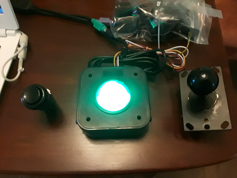
- 8-way arcade joystick
- Trackball w/ PS/2 interface
- Happ style buttons
- 12 key numeric keypad
I will be salvaging connector and cable from my broken controllers. I will use an AtMega microcontroller to read the PS/2 trackball, and emulate the Atari 5200 Trakball. (I hate their silly spelling) The Trakball contains a circuit that converts a train of pulses from the rotary encoder to an analog value, emulating the joystick. The plan is to have the Atmega read the ps/2 protocol, and output a PWM signal, which can then be integrated in a similar manner.
Links
5200 Trackball technical information
Atari 5200 System and controller schematic
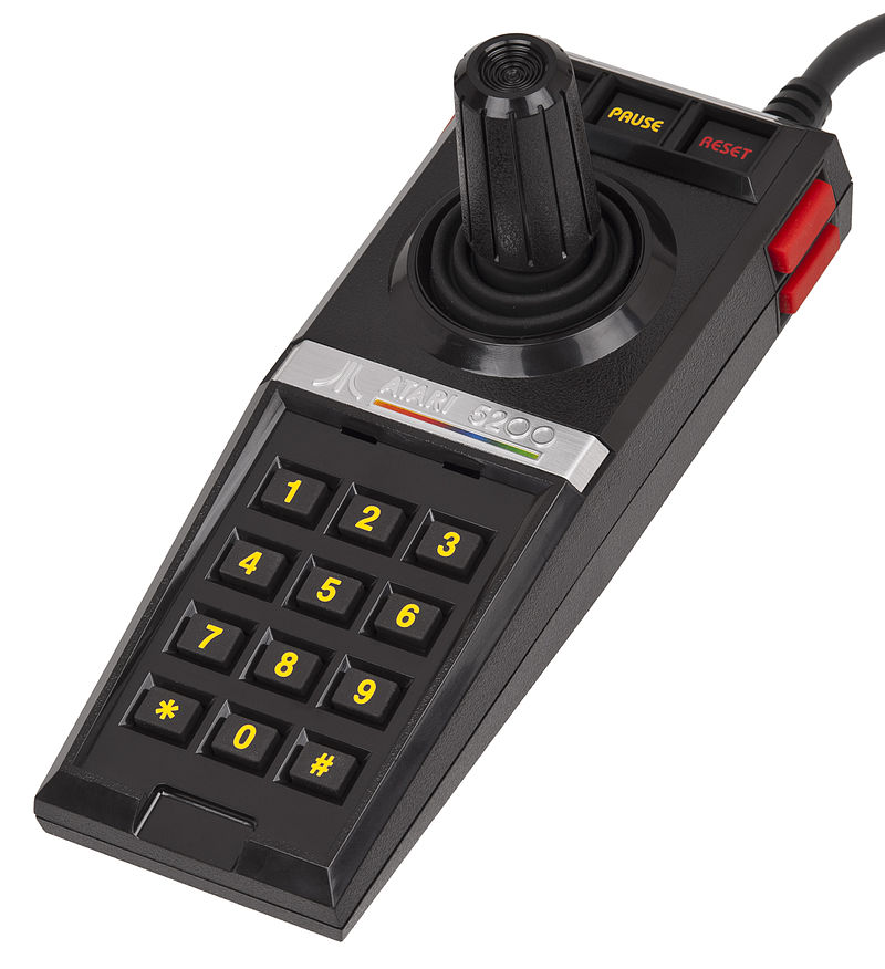
Image Credit: Evan-Amos, Public Domain, Wikimedia