 |
Introducing the
Radio Shack Special
Note: This is the original
version.
See the new version of the Radio
Shack Special on Patrick's Web Site
Original site is dark, but link goes to archive.org
|
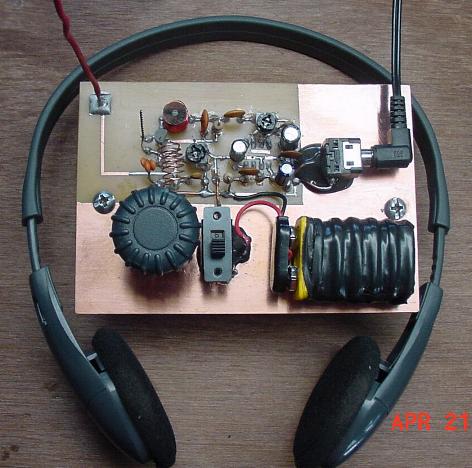
For a detailed view, click here
I have browsed the world wide web many months in search of a one transistor FM receiver. I have seen a couple... but they were always attached to some sort of added device., such as another IC or another transistor for amplication in the receiver itself.. Through my continued quest of searching for that 'too good to be true' one transistor, I happened to run across a super-regenerative receiver, by Charles Kitchin, famous for his vast knowledge of regenerative designs. I printed out the schematic and made it. It turned out extremely well...
With much experimentation and 'un-design'...as I call it, I began taking away a component of the 'newly-made' receiver...one by one a component came off. Down to 11 components left on the receiver itself...it finally stopped. I then put component number 12 back. I must say that without sacrificing or comprimising for senstitivity, selectivity and audio output...this little gem is still shining it's light as bright as it can. I then continued to experiment and re-design a small SOURCE Coil for the receiver. Standing no taller than 1/2 of an inch and 8mm's in diameter, this homemade coil is doing its' job just fine. I also made a homemade fixed capacitor in the 12 component count. Substitution came around again and replaced the telescopic antenna with a 10 inch 22 gauge magnet wire. Not too bad for a fully functional FM receiver. Of course, to beef up the audio, an LM386 circuitry was added to the output of the receiver. In fact, the LM386 component count rivals that of the receiver itself.
Large View of the Receivers' 12 Component Count
 |
| 1 DRAIN/SOURCE Capacitor | 7 1K Gain Control |
| 2 The Antenna | 8 MPF102 Transistor |
| 3 DRAIN Capacitor | 9 SOURCE Coil |
| 4 Tuning Capacitor | 10 .0047uF Capacitor |
| 5 DRAIN Coil | 11 10K Resistor |
| 6 .001 Capacitor | 12 .1 Capacitor |
And so became the 'birth' of The Radio Shack Special...the name given to it because all of the components may be purchased at your nearby Radio Shack store (except for the tuning capacitor, although that can be found in an AM/FM tunable radio) together with all the experimentation that one can find...increasing sensitivity...finding other areas of interest in the VHF spectrum...altering the uH's of the SOURCE coil for better signal clarity when spanning other parts of the VHF spectrum...adjusting antenna heights for the best overall reception...adding taps to the DRAIN Coil to further increase sensitivity...putting in a larger audio amplifier to drive a loud speaker ...increasing or decreasing the DRAIN/SOURCE capacitor as still another way to acheive added sensitivity...enclosing the entire unit in a metal case for that personal touch...the list goes on and on. My end goal was two-fold...1)To make an extremely simple basic FM receiver with just one transistor 2)to get hold of all the components at your local or nearby Radio Shack store, thereby surrendering this to anyone who is willing to learn a bundle of knowledge through experimentation and hence, laying down all the tools needed for a splendid in-depth project.
As time went on I started posting the little jewel on many different electronic forums...as you probably already know. The first person to make this was a fellow (now friend) named Pedro. He not only made it...but designed a beautiful looking enclosure to the finished project. Take a break right now and go to the webpage "Pedro's Maiden Voyage with the RSS". When Pedro completed his project, this is what he had to say about it:
you don't need to build complex technicalities ...such as slope or phase detectors required for fm reception. The amazing simplicity of this super regenerative receiver brings you the pleasure of hearing your favourite FM stations and at the same time the satisfying sense of personal achievements.
...Pedro
RADIO SHACK SPECIAL
Introduction.............................................................................................Page 1
Get All of the Parts First.........................................................................Page 2
Making the Homemade Devices............................................................Page 3
Making the PCB (front and back)..........................................................Page 4
Component Placement.............................................................................Page 5
The Ordered Way of Soldering the Components..................................Page 6
The First 'Turn-On'................................................................................Page 7
The Radio Shack Special Schematic.....................................................Page 8
In this exciting project, not only will you have a very unique one transistor FM recevier, but also be in-store for making home-made air-core coils and a home-made fixed capacitor. And even more than that, when you finish 'your' project, your journey has just started. With your now-working FM receiver, you can start experimenting with many wonderful things that I had mentioned. Once you have mastered all these things...you will surely have a better grasp on the whole concept of what 'hands on' experience truly is. It is a very rewarding experience when you have gone into the unknown...taken roads that you have never taken before...roads that lead you to knowledge of things that you would have never thought possible...and all on your own!
I did send an e-mail to Charles Kitchin and told him of the 'un-design' I had given to one of his designs. In fact, he had said that back in the earier years, there was a certain TV company that had used that same 'un-design' method. If you would like to see just where the birth of the Radio Shack Special came from, take a trip now to see Charles' original schematic of his super-regenerative receiver. Just click here.
Throughout this website, you will also find other nice projects. Some by me and some by my 'newly-founded' friend...Pedro. We have put all these wonderful projects out to you in hopes that...just like fishing, if you have never experienced the joy of catching your first fish...you will never know what its' like. The same goes for these projects... we have all the 'bait' here for you to take...but it will be left up to you for the taking. I still routinely go and post my Radio Shack Special to as many radio/ham/electronic forums as I can..not to mention always updating the website from comments and/or advice by recent visitors. I am again, glad to see that you have managed to get here. Pedro would concur with my feelings. With all that said, continue the voyage into the wonderful world of the single and proud MPF102 transistor.
Most of the time it is the simple things that catch our attention...realizing later that much was learned from it.
...your friend, Patrick
Get All Of The Parts First
Let us begin the project...start by getting all of the parts needed as shown below. Once you have them, go ahead and proceed.
| Hacksaw...fine tooth (Hardware Store) | ...to cut PCB to required dimensions. | |
| Finest Steel Wool (Hardware Store) | ...in preparation for dry transfers. | |
| 5/16" Standard Threaded Bolt (2"long) | ...to make DRAIN Coil. | |
| Drill with 1/32" drillbit | ...to make the 8 holes needed for LM386 | |
| Antenna (10" of 22 gauge magnet wire) | ...for the best possible reception. | |
| Magnet Wire (RS #278-1345) | ...for the homemade coils & capacitors.. | |
| 47K Potentiometer (RS #271-283) | ...for volume control | |
| .0047uF Capacitor (RS #272-130) | ...component | |
| .001uF Capacitor (RS #272-126) | ...component | |
| .1 Capacitor (RS #272-135) | ...component | |
| LM386 Audio Amp. Chip (S #276-1731) | ...For amplification of audio signal | |
| .047 Capacitor (RS #RSU 11298296) | ...component | |
| Audio Jack 1/8" dia. (RS #274-249) | ...for headphones | |
| 10uF/16v Capacitor (RS #272-1025) | ...component, observe correct polarity. | |
| 100uF/35v Capacitor (RS #272-1028) | ...component, observe correct poliarity. | |
| 220uF/35v Capacitor (RS #272-1029) | ...component, observe correct polarity. | |
| 10K ohm Resistor (RS #271-1126) | ...component | |
| 10 Ohm resistor (RS #271-1101) | ...component | |
| Dual Mini Board (RS #276-148) | ... template for drilling holes for LM386. | |
| Etching Solution...16 oz. (RS #276-1535) | ...for devloping the "dry transfer" PCB. | |
| Dry-etch Transfers...(RS #276-1490) | ...for making circuitry routing on PCB. | |
| 40-Watt Soldering Gun (RS #64-2071) | ...for soldering of components to PCB. | |
| Rosin Core Solder (Auto Zone) | ...needed to secure components to PCB. | |
| DIP IC Socket (RS #276-1995) | ...for the LM386 to be inserted into | |
| 4.7pF Disk Capacitors (RS #272-120) | ...DRAIN Capacitor (3 is needed) | |
| Salvaged AM/FM Tuning Capacitor | ...from an AM/FM Tuning Radio | |
| PCB (Radio Shack #276-1499A) | ...for the makings of the circuitry board. | |
| 1K Potentiometer | ...for the gain control of the receiver |
Making The Homemade Devices
The following four devices must be strictly made according to plan. It is these devices, that if not made to exact trueness, will warrant a 'no-go' situation, when it comes time to turn the unit on for the first time. I will go into great detail in how to make each and every one of these items. I will begin with the SOURCE Coil....then the DRAIN Coil...and last, the DRAIN/SOURCE Capacitor. Let's us begin:
The SOURCE Coil
You will need 4 items to make this coil. 1)A drill 2)A 1/32" bit 3)a round non-metallic form, whose measurement in diameter is exactly 8mm's. I used a round wooden pencil, in which the diameter was exactly 8mm's. 4)30 gauge enamel-coated (red) magnet wire:
Begin by drilling a 1/32" hole somewhere toward the center of the non-metallic form. Take the end of the 30 gauge magnet wire and place through the hole of the form. Let is stick out 1/2 inch and then make a 90 degree bend with it. This will keep the wire in place while you are making your wraps around the form...make 26 wraps. Make tightly wounded- wraps of wire around the pencil. Make sure they are good and tight. When you get to your 26th wrap, take the drill and make another hole right beside the last wrap. Then cut the magnet wire and place thru this second hole. Make sure the wire extends out of the hole 2 inches. Then make a 90 degree bend in the wire so as the wire can hold itself in place. The coil should be good and tight and will not come undone. Trim both ends of the wire as shown in the picture below. The picture is what is should look like just before soldering into place on the PCB. Once you have finished making it, place it aside until it is time to solder it on the PCB.
 |
The DRAIN Coil
You will need two items to make this coil: 1) 22 gauge magnet wire 2) 5/16" standard threaded bolt. Cut 15 inches of 22 gauge manget wire off the spool. Take the 5/16 inch standard threaded bolt and wind 7 complete wraps of the magnet wire into the threads of the said bolt. Gently unscrew the 'now-made' coil from the threaded bolt. Be careful not to alter the 'spacing' of the newly made coil. It is from this 'set' form, together with the tuning capacitor, will you be 'right' on the FM band.Now from the top of the coil to the bottom of the two legs....it should be right at 3/4 of an inch. The picture below is what is should look like before soldering to PCB. Once you have finished making it, place it aside until it is time to solder it on the PCB.
 |
The DRAIN/SOURCE & DRAIN Capacitors
The DRAIN/SOURCE Capacitor and the DRAIN Capacitor are devices that you will make. You also have another alternative: You can substitute the homemade DRAIN capacitor with 3- 4.7pF capacitors soldered in parallel. You can also substitute the homemade DRAIN/SOURCE capacitor for a single 4.7pF capacitor. Either way you would like to tackle this...is left up to you. If you decide to make your own, below is the construction of both capacitors.
Items needed will be 26 gauge magnet wire and pliers. Make two identical capacitors: One for the DRAINSOURCE Capacitor and the other for the DRAIN Capacitor. Start by taking 6 inches of 26 gauge magnet wire. Double it and then put both ends of the wire into the teeth of the pair of pliers. Grab hold of both ends of the wire 1/4 of an inch the way up. Now with one hand, hold the pliers and with the other hand, grab the other end of the doubled-up wire and making 15 complete turns....your hand typically cannot make a full turn...so telling you to make 30 half turns would be easier to say and accomplish. Your doubled-up wire will get mighty twisted...but that is what you want to happen, just keep it straight while making the turns. Once you have made your last turn, look at the picture below for the rest of the constuction.
 |
Once you have made one homemade DRAIN/SOURCE fixed capacitor, make another one just like the first one. There will be two of these homemade capacitors needed for the completion of the Radio Shack Special. One for the DRAIN/SOURCE Capacitor and the other for the DRAIN Capacitor. Place both of these capacitors aside until the time comes for soldering all of the components on the PCB.
The Salvaged Variable (Tuning) Capacitor
Although Radio Shack does sell (by ordering) a couple of variable capacitors, I am sure you can scrounge around and find an AM/FM tunable radio that someone doesn't want anymore because it doesn't work or the like. Once you have managed to find one, make sure you keep the turning knob that came with it...on it's shaft. Let us begin the understanding of this little device and how it is to be connected in the circuitry.
The tuning capacitor has typically 6 leads coming from its' sides. Three leads on one side and three leads on the other side. We are concerned with using just two of the 6 leads. Below is a representation of the variable capacitor...this will give you the directions needed to find the 'right' two leads:
 |
Notice that the variable (tuning) capacitor has 6 terminals. I will present to you how to find the correct '2' terminals needed to catch the span of frequencies from 87 Mhz to 107 Mhz. The center terminal on these devices are always 'ground'. Notice that there is a ground (always the middle leg) on one side of the capacitor and there is another ground (again, always the middle leg, no matter what side of the capacitor you are using) on the opposite side of the capacitor.
One side of the capacitor is the 'hi' side. The opposite side of the capacitor is the 'lo' side. In order for the Radio Shack Special to scan through 'all' of FM band, you must find the 'hi' side. In order to do this, once the unit is working well, you will have to try both sides and find out what side will 'catch' the whole FM spectrum (87-107 Mhz). The 'hi' side will catch the whole spectrum, and a little bit more on both ends...but the 'lo' side will only catch a portion of the FM band...you will come to figure out which one will do the job well.
Now, again, look at the above picture. Let's take the top side of the capacitor. There is #1, ground, #3. Let's suppose this is the 'hi' side. It doesn't matter if you use ground and #1 or ground and #3. Either set of terminals will produce the correct pF's you need. This applies to either side. It doesn't matter what 'end' terminal you use with ground...just as long as you have the correct 'hi' side...and again, that will be figured out when you try both sides on the receiver. So connect one side to the unit, that is, if you were using the top side of the picture, you can use #1 and ground or #3 and ground...if you find out that this doesn't span the complete gammit of the FM spectrum...it will be other other side...again, it doesn't matter if you use #4 and ground or #6 and ground...if this would be the 'hi' side...either end terminal and the ground will work the same.
Also, remember that the 'ground' terminal of the variable (tuning) capacitor must go to ground on the PCB. Of course the other terminal on the capacitor will connect up with the DRAIN Capacitor in series.
This is a new and updated version of the PCB. Since this project deals with VHF, makings of the PCB should be adhered to. The concern is the electrical copper routing. If you make an 'exact replica' of the electrical routing below, you should have NO trouble at all when the first 'turn-on' is initiated. Below will be a 'general' description on how to make the PCB. If you would like to know the complete process on how I made mine with Dry Transfers, please go to this special section that I have made...for a thorough explanation on...
The Complete Makings of the PCB Using Dry Transfers
otherwise, continue on down with a general (non-detailed) construction of the Printed Circuit Board...
The Printed Circuit Board (PCB)
 |
There are many ways to skin a cat. I will tell you how I skinned this cat in order for you to have at least one idea of how to make the above PCB. Print out the above picture first. When printed out, make sure it conforms to the exact measurements as shown in the picture. If not, send the document to a Paint or Graphics Program in order to sqeeze or stretch it to the correct dimensions. Once this is done, make a print out. This print-out will be used as a template for making exact routing placments.
Next, cut a double-sided PCB to 116 mm's by 80 mm's. Once this is done, place the PCB template sheet of paper and cut it out. Follow the heavy rectangular line that encompasses the template...this heavy black line measures out to be 116 mm's by 80 mm's also. Then place the cut template directly over the 'freshly-cut' PCB. It should fit perfectly over it. Now tape it down so it cannot be moved.
Take a light hammer and center-punch (sharp tip or a sharpened nail) and lightly tap (tap on the center-punch ONLY one time) on each 'tiny' white dot that you see on the template. Use the picture below for guidance in making sure that you center-punch ALL the holes. When using the hammer to tap on the center-punch, take a discarded piece of PCB and practice with a 'one-tap' hit so that you can actually 'see' the depression, once you have made the hit. It will take a certain pressure hit with the hammer, but you will will get the hang of it on how much of a hit you need in order to see 'all' the depressions once you get thru. These depressions will be the 'guide' for you in order to place your electrical routing of dry transfers. Each depression is either a solder point or the corner of an electrical route. When you have finished with making all of the taps on the tiny white dots, you will then drill your 10 holes. Eight holes will be for the LM386 low profile insert and the remaining two holes will be for some sort of mount that the PCB can be placed on. Take a good overall look at the picture and then start.
 |
 |
The most critical aspect of the whole project is to conform your electrical routing the same exact way you see it in the above PCB drawing. When printed out, the PCB drawing should be the exact measurements as shown in the picture. If not, then transfer the picture to a Paint or Graphics Program and sqeeze or stretch to adjust for true measurements. One this is done, organize yourself into 'mimicking' the routing as close as you can. This precept should be adhered to before placing components on the board.
Component Placement
There are two charts below: One is the Component Placement Guide and the other is the Component Identification and Value Guide. With these two charts, you should have no problem in knowing which component goes where. Below the charts is a full explanation of how to proceed in soldering all of the components.
Component Placement Guide
 |
Component Identification and Value Guide
| 1 Antenna - 10 inches of 22 gauge wire. | 12 220uF/10v Electrolytic Capacitor |
| 2 SOURCE Coil | 13 .047 Disk Capacitor |
| 3 1K Gain Control Potentiometer | 14 10uF/50v Electrolytic Capacitor |
| 4 .0047 Disk Capacitor | 15 10 Ohm Resistor |
| 5 10K Resistor | 16 Battery Leads |
| 6 .1 Disk Capacitor | 17 .001 Disk Capacitor |
| 7 47K Volume Control Potentiometer | 18 Variable (Tuning) Capacitor |
| 8 .001 Disk Capacitor | 19 DRAIN Coil |
| 9 100uF/10v Electrolytic Capacitor | 20 2 4.7pF Capacitor in Parallel |
| 10 .047 Disk Capacitor | 21 DRAIN/SOURCE Capacitor |
| 11 Audio Jack | 22 MPF102 FET N-Channel Transistor |
The Ordered Way of Soldering the Components
1) Solder in the 'low-profile' eight pin socket (it goes in from the back side) that will be used to insert the LM386. Then insert the LM386 into the socket. Then flip the PCB back to the front-side.
2) Make your support for the PCB right now. Use the two mounting holes for securement. It may be placed on an ordinary piece of thin (1/8" thick) wood, like paneling wood. Let it rest about 1/2 of an inch high from the wood. Any way you would like to mount it would be OK. Just don't use a metal structure, as this could have a definate effect on the overall performance. Later, once you have the receiver working well, you may then experiment, by enclosing it into a metal box of some sort for that 'professioinal' look. Again, be watchful for differences in performance when bringing metal close to the unit.
3)Next, solder in the MPF102...then the 2 potentiometers...then the SOURCE Coil...then the DRAIN Coil.
4) Next, you will put in the DRAIN Capacitor...which is a culmination of three capacitors...that is, 2 4.7pF capacitors and your homemade DRAIN Capacitor...connect all three of these capacitors in parallel before soldering, by twisting the legs around each other. There is only one set of soldering terminals on the PCB for all three capacitors...make sure you have put them all together in parallel before soldering.
5) You will start soldering the rest of the components (except for the tuning capacitor, the switch, the audio jack and the 9 volt battery)by...starting from the right side of the PCB...that is, the audio section will be the starting point...as you solder each component in, keep moving left, until you get to the last component, which should be the .001uF capacitor, which is connected to the DRAIN Coil. This order should be met, otherwise you will find yourself cornered and having no way to insert the soldering gun tip to solder a component. This way, it will keep an area always open (to the left side of the component) so that your soldering gun can easily make the soldered contact.
6) Next comes the placement of the tuning capacitor...the ON/OFF switch...the Audio Jack...and the 9-volt battery. I use the new '4-minute' JB Weld that may be purchased at your local Auto Zone store or Wal-Mart. Go ahead and place the tuning capacitor in the appropriate place and make its' connections. Then take the switch and make its' connections, then the Audio Jack with its' connections and then the connections for the 9-volt battery. You may look at the drawing below to get an idea of how everything looks, once the rest of 'these' components are installed.
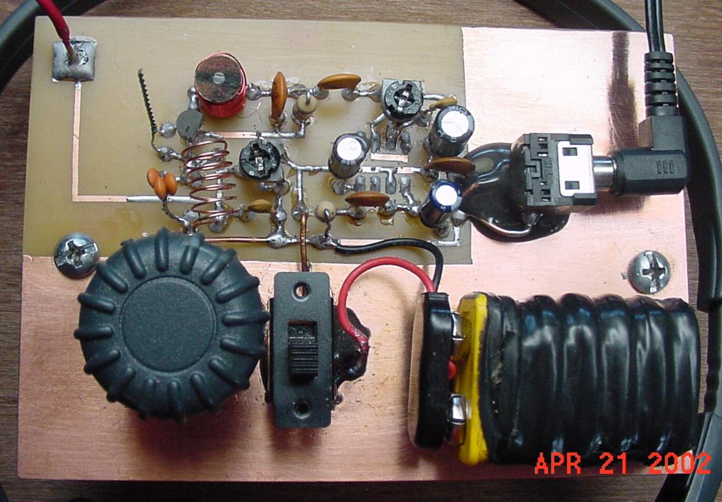
The 'Finished' Look
 |
You may now apply your '4-minute' JB Weld to the tuning capacitor, switch and audio jack. I used a small patch of velcrose to keep the battery in place.
Take a good overall look of the PCB. Look and inspect for solder droppings, electrical routing 'breaks' or bad soldering on components. This will be your final inspection before turning the unit on.
The First 'Turn-On'
Here we go...
With a 'fresh' 9-volt battery in place and switch to OFF and a 'standing tall' 10 inch 22 gauge magnet wire in place for the antenna...set the unit accordingly...make sure the 1K potentiometer is turned all the way to the right...make sure the 47K potentiometer is turned all the way to the left, then turn 1/4 the way to the right...turn the variable (tuning) capacitor all the way to the left....then turn it all the way to the right...notice the distance it covers...then set that distance to half...exactly in the middle. Adjust the DRAIN Coil (by sqeezing it or stretching it) to exactly 10 mm's.
With the headphones on the ear's and with your potentiometer tool (the tool needed to adjust both potentiometers) in hand, turn the receiver ON!
One of two things will happen...
You will either receive good clean static...
Or you will be on an FM Radio Station...
If everything went according to plan...it should have come on.
Now, not knowing whether you have the right set of terminals on the variable capacitor connected to the receiver, try both sides now...by adjusting (stretching or sqeezing) the DRAIN Coil, see if you can capture all of the stations on the FM band...if not, turn to the other side of the variable capacitor and try that side. One side will give you the full range.
Once you have found the right side, turn to the furtherest station to the left (that would be around 87 Mhz)...then get into between stations...you should have good clean static...now take your potentiometer tool and begin to turn the 1K pot to the left, slowly, until you hear the static increase...as you keep turning the static will then decrease again and then the unit will go out. When it does, then turn back to the right until you hear that loud static again...that is where you want the pot to remain. There is a certain area where the static gets the loudest, right before it goes out...try to find that spot. Once you have it, you may know breeze through the stations and also using your volume control (47K pot).
There you have it, my friend! I hope everything went well and that you are experiencing the many benefits from the...
Radio Shack Special!
Troubleshotting the Radio Shack Special
Along the way of making it, you may unhesitantly e-mail me for whatever concern or advice or question you make have concerning the project. If you have come this far, and it doesn't perform at all...or for that matter 'well', it would seem there could be another culprit lying in the circuitry there to challenge you a little more. Re-look at everything you went through...correct polarity on capacitors...correct circuitry placement...droppings of solder in between two separate electrical routings...a break in an electrical routing...using a continuity tester, make sure both of the homemade capacitors are not touching at the top where you had made your cut with the cutting pliers (sometimes, this happens when you make a cut on the double-twisted wire. It sometimes tends to mesh itself together. Again make sure you have NO continuity between the twisted wire. You will have to take the capacitor out of the circuitry to check this...Also, touch the .1 fixed capacitor on the receiver output to see if you hear a hummmm in your headphones. This would let you know if the audio section is up and running. If you do not hear a humm when you touch this capacitor, increase the volume and try again. Still if no humm, then your audio section will have to be re-looked at again...Do please send me a line ifa culprit is still there...two heads are always better then one!
Below is the schematic layout for the Radio Shack Special. Although one needs to pay strict adherence to following the exact routing of all the electrical circuitry as shown on the PCB, this schematic is intended just to show how the components are arranged in relation to one another.
 |
...and let the project begin!
You may e-mail me at...mailto:braincambre500@yahoo.com
Last updated 12 December 2004