
Post War to Pre War FM Band Receiving Converter
A unique"bilateral" mixer design
By Andrew Mitz
Reprinted from:
Radio Age - July 1999
A Matter of Taste
Charlie Rhodes’ power supply article ("Regulated Power Supplies for Old Battery Radios" Radio Age, Vol. 24, Number 5) got me thinking. For those of you who missed his article, Charlie described a power supply design that uses a mix of modern day semiconductors and vacuum tubes. His motivation was listening to an "oldies" station on a 1920’s AM radio. Charlie’s listens to WWDC AM. My favorite radio station is WWDC FM, which plays modern rock. In collecting each of us has his own tastes. I eschew oldies radio stations and using vacuum tubes in new designs; whereas these suit Charlie just fine. My taste is FM, solid state, and rock music. Accordingly, this article presents a design for listening to present day FM stations on a prewar FM set based on a MOSFET transistor and a TTL (transistor-transistor logic) packaged oscillator. Someone else might have done it with vacuum tubes, but this design suits me fine. It is all a matter of taste.
Problem
My FM radio station of choice is at 101.1 MHz. I specialize in FM only radios, so listening to this station is no problem on most of my sets. But prior to WWII, the FM radio band covered 42 to 50 MHz. These prewar FM radios are nearly useless. Turn one on and most likely you will hear nothing. You can receive old cordless phones and some baby monitors, if you don’t mind reduced volume. The prewar sets are wide band FM. The narrow band consumer devices don’t climb very far up the detector’s slope, so the audio level is low. Moreover, after a few cheap party thrills the fun of listening to the cordless telephone wears off and you are stuck with finding some other use for the set. Converters to bring prewar FM onto the modern FM band (88 to 108 MHz) were manufactured by Hallicrafters late in the 1940’s. I don’t know of any others, and I am still hunting for a Hallicrafters CN-3 or CN-5 for my own collection. I have not even found one to photograph for my web page (www.somerset.net/arm/fm_only.html). I was contacted by one person with a CN-1, a converter that fits inside a console and steals power from the audio output tube. Apparently his works pretty well. But I digress. The point is that commercial converters are hard to find. So early in my quest I realized that a home brew converter was my only real hope for grooving to Grunge Rock on a Stomberg Carlson 505H.
Solution Space
I did not even consider using vacuum tubes for this design. Rather, I began by considering a number of discrete component and integrated circuit frequency mixing schemes. A 3N204 dual insulated gate CMOS transistor seemed a reasonable start. This low cost transistor runs off a 9 volt battery, has low noise, good conversion gain, is easily biased, and was in my spare parts collection. Similar transistors, like the 40673, will also work. The local oscillator design was a bit more tricky. The prewar band is 8 MHz wide and the modern FM band is 20 MHz wide. I considered a L-C oscillator with a variable capacitor or inductor to help cover all 20 MHz. That is how the Hallicrafters works. However, I did not want any headaches with frequency stability. Another thought was to use a couple of different crystals from my extensive quartz collection, but my intention was also to provide a design that others could easily duplicate.
I started a quest for the right crystal. The microprocessor crystal section of numerous electric parts catalogs provided interesting bathroom reading for a day or two. The reading proved fertile ground for selecting the local oscillator source: a 28.322 MHz TTL oscillator. A TTL oscillator generates a stable square wave rich in harmonics. It has only 3 pins: power (5v), ground, and output. It is in a silver package that plugs into a 14 pin integrated circuit socket. What could be easier? The second and fifth harmonics of this oscillator were reasonable mixer local oscillator injection frequencies. The design was afoot.
You take the High Road, I’ll take the Low Road
When it comes to mixing, the first question is whether to use high side or low side local oscillator injection. With high side injection the local oscillator is higher in frequency than the signal you wish to receive. The received signal frequency is subtracted from the local oscillator frequency to give you an intermediate frequency (IF). In my case, the prewar FM band is the intermediate frequency. High side injection with the TTL oscillator would be at the fifth harmonic (141.61 MHz). With the FM radio able to hear 42 to 50 MHz, the mixer would provide an 8 MHz segment of the modern FM band from 91.61 MHz to 99.61 MHz:
|
Local Oscillator |
± |
IF |
= |
8 MHz segment of Modern FM band |
|
141.61 |
- |
42 (low end) |
= |
99.61 |
|
141.61 |
- |
50 (high end) |
= |
91.61 |
One disadvantage with this scheme is that the low and high frequency ends of the band are reversed. More importantly, this range misses my desired station at 101.1 MHz. Forget high side! Low side injection places the local oscillator signal below the signal you wish to receive. The received signal frequency adds to the local oscillator frequency to produce a copy of the signal at the IF frequency. The second harmonic of the TTL oscillator is at 56.644 MHz. Taking advantage of this second harmonic:
|
Local Oscillator |
± |
IF |
= |
8 MHz segment of Modern FM band |
|
56.644 |
+ |
42 (low end) |
= |
98.644 |
|
56.644 |
+ |
50 (high end) |
= |
106.644 |
Low side injections gives more promising results. The receiver would hear from 98.644 MHz to 106.644 MHz. This range includes my favorite station, so low side seems to be the solution. Right? Maybe not.
Why not use both low and high side injection? If we mix with both signals we get an interesting effect. AM radio people would never try this trick. Heterodyning of AM signals gives annoying beats during AM detection. FM is quite different. When two FM stations overlap, the slope detector tends to follow only the stronger of the two stations. This FM "capture" effect means that there is one clear winner. Using the capture effect to our advantage, we can inject both the second and the fifth harmonics and get both regions of the modern FM band. Figure 1 shows the complex mapping of the modern FM band onto the prewar band for each. The result allows us to receive stations from 91.61 MHz to 106.644 MHz. Thus, "bilateral mixing" yields 15 MHz coverage without requiring multiple crystals or a VFO. The band maps a bit funny and the scheme can occlude weak stations that overlap with stronger ones. My target station has a big transmitter, so I’m in Fat City.
If you are an astute mathematician, you may have noticed the theoretical flaw in this design. Fourier analysis shows that a square wave has only odd harmonics. Where can the second harmonic come from? The answer is in the details of the design. A little capacitance and resistance in the output of the square wave oscillator will distort the square wave enough to provide a strong second harmonic.
The Details
The schematic, Figure 2, shows my implementation. The TTL oscillator (OSC1) and the MOSFET (Q1) do most of the work. A few tuned circuits and a zener diode are all that are necessary to complete the design. MOSFET transistors have many of the characteristics of vacuum tubes. Q1 has two gates, G1 and G2, that act like control grids. The source (S) acts like the cathode; the drain (D) acts like the plate. In this converter design G1 is biased at ground potential through T2. G2 is held above ground by the voltage drop across R4 (via R3).
Q1 operates as a mixer. G1 gets the modern FM band signal from the antenna by way of a tuned circuit (T2 and C11), centered at 101.1 MHz (of course). G2 gets the local oscillator signal. The drain lead of Q1 has the output (IF) tank circuit (T1 and C3) centered at 46 MHz, the middle of the prewar FM band. Two local oscillator signals are derived from OSC1. OSC1 drives L1 and C9, a series tuned circuit to trap the unwanted third harmonic of the oscillator near 85 MHz. L2 and C6 are tuned to the fifth harmonic of the oscillator (141.61 MHz) to enhance it. C6 also dampens the square wave enough to produce a strong second harmonic at 56.644 MHz. The local oscillator signals are capacitively coupled to G2 of Q1. If we did not want the second harmonic for mixing, G2 would have been inductively coupled to L2. T1 of the tank circuit has a 4 turn link coupling to provide a connection with the prewar set.
All the coils except L1 were wound on whatever miniature coil forms were laying around. L1 was air wound. If you don’t have a collection of coils laying around, try some stock Toko coils from Digi-Key (1-800-344-4539, www.digikey.com). I tuned each coil/capacitor to its target frequency with a grid dip oscillator before connecting it to the circuit. I then used the grid dip oscillator near Q1 as a passive wave meter to adjust the 85 MHz trap for minimum signal at that frequency.
Q1 tolerates nine to twelve volts without difficulty. OSC1, like all good TTL circuits, requires 5 volts. R2 and D1 keep the oscillator humming happily at 5 volts regardless of the input voltage. D1 could be removed if you always operate from the same voltage and choose R2 to maintain a 5 volt drop across OSC1. OSC1 draws nearly all the current of the circuit, about 35 ma. A healthy sprinkling of .001 m f capacitors provides bypassing for the power connections.
Construction
Most of my solid state projects have been built with surface mount or through-hole construction using standard circuit boards. In the case of this receiving converter, I chose the method shown in the photograph (Figure 3). This method employs copper clad circuit board for shielding. One large piece of board was used as the main board. I cut up other pieces for the partitions. The partitions were mounted by forming a solder seam between each partition and the main board.
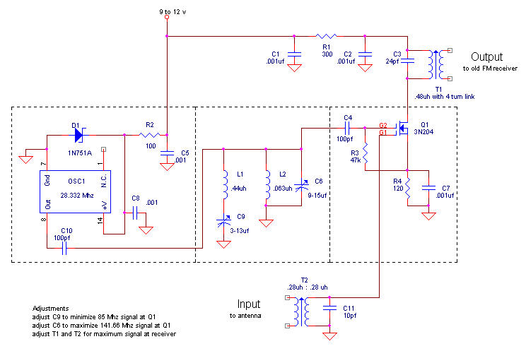
Figure 2. Schematic of the modern FM band to prewar FM band converter. Dashed lines indicate separate shielded compartments.
Looking at the photograph, the rectangular component on the far right is OSC1. Adjacent to the oscillator section is the filter section. It houses the 85 MHz trap and the 141 MHz tuned circuit. Well, not entirely; C6 fit more easily in the mixer section, so I put it there. Q1 sits upside down in the mixer compartment with each of its four leads attached to standoffs. The input and output tuned circuits each have their own cordoned-off sections. Connections between sections are made through holes in the partitions. The input BNC connector is held to the copper clad surface with a seam of solder much like the partitions; the output BNC is soldered to a standoff. The power leads are connected to a 9-volt battery through a tiny slide switch. The battery is spot soldered to the circuit board to hold it in place.
Performance
With just a short piece of wire connected to the converter and a scrap piece of coax cable going to the Stromberg Carlson 505H, stations came roaring in the first time I fired up the converter. Sensitivity improved with a little tweaking of the input and output tuned circuits. It brings a big smile to hear this old prewar set come alive with broadcast stations!
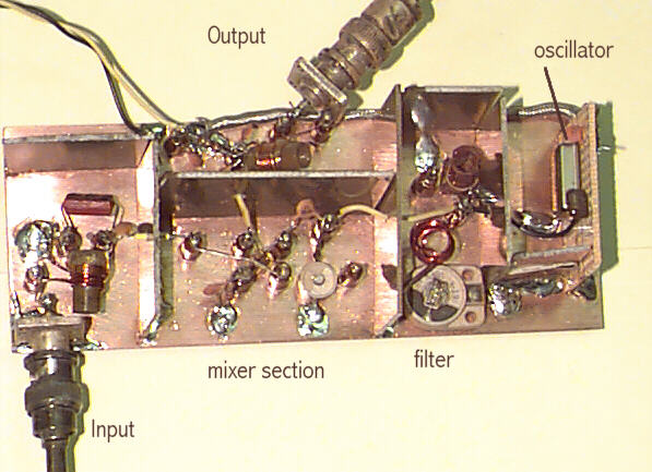
Figure 3. Photograph of converter prototype. Main board and shields are fabricated from copper clad circuit board stock.
Your Turn
I teased Charlie Rhodes a bit at the beginning of this article, but the real take home message is that as collectors, our personal histories are as diverse as the histories of the items we collect. My tastes in collecting and design have brought me to a place quite different from Charlie’s. As a young ham radio operator I could not afford the really nice equipment, so I learned to convert war surplus, restore old equipment, and to design and build my own. By the time I entered engineering school vacuum tubes had been relegated to the appendix in most text books. My introduction to radio restoration did not begin until many years later, and started with the overhaul of a 20-tube Philco from my grandfather’s estate. Rock music, and the image of a Granco 601U sitting in my mother’s kitchen, brought me to my current passion for FM only radios. Who else can claim these roots? These historical vagaries have shaped my collecting style.
Your style differs for its own reasons. Each of us brings a unique point of view and expertise to radio collecting. Collecting benefits from this diversity. I challenge each collector out there to examine his own interests, see what you have to offer, and share your tastes here in Radio Age. This is my first article on radio collecting. Now it is time for yours.
Acknowledgments: Special thanks to Frank Putnam, Dan Cohen, and Roy Morgan for critiquing early drafts, and to Ravi Goonasekeram for his scholarly theoretical insights.
Copyright © 1999 LTJ Designs