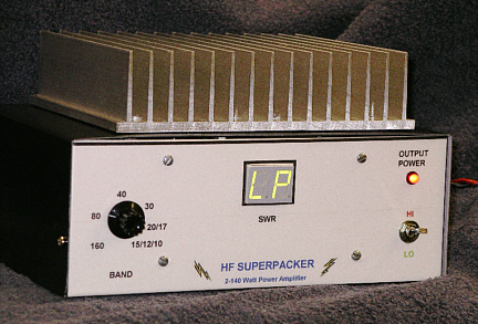
The SuperPacker 100 Watt HF Amplifier
from QST magazine, December 2005
Jonathan Gottlieb WA3WDK and Andy Mitz WA3LTJ
Builders' Web Page
The SuperPacker HF Amplifier project was published in the December 2005 issue of QST magazine by Jonathan Gottlieb WA3WDK and Andy Mitz WA3LTJ. This web page is intended as an aid for people building the amplifier. It is based on feedback from other hams who have built the SuperPacker, or at least tried! In some cases, the notes are taken word-for-word from email sent to us.
Obtaining the article
To get a copy of the construction article, you must have been a member of the ARRL in December 2005, or purchased a back issue from the ARRL (http://www.arrl.org). The article starts on page 31.
Obtaining the parts
The article discusses a source for most of the parts. Notes below address some of the parts procurement problems. We hope someone will provide a complete list of parts and sources. That would make the project easier for others.
Notes on the PIC SWR wattmeter
Here is a bigger shot of the partially-assembled pick-up board shown in the article. Note that this board is actually an earlier board that was printed mirror image from its proper orientation. When you get a board for FAR circuits, the traces should be corrected to match the original article.
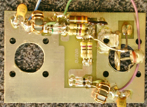
R-14 and R-15 (100 ohm, 1/4 watt) on shown on the schematic, but not in the parts list of the original article. R-8 is shown as a dip resistor network, but individual resistors will work as well.
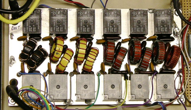
FARA HF Amplifier Low Pass Filter Board
There are ferrite beads shown on the schematic between the board and the band switch. The beads are slipped over the wires near the circuit board. These beads can be purchased from Amidon Associates. The photograph in the SuperPacker QST article shows the FARA printed circuit board with the original FARA coils and capacitors. The photograph here shows the same printed circuit board with the larger Amidon cores and new capacitor values from Table 1.
SuperPacker QST Article
Errors:
1) The transistors listed as IRF-454 should be MRF-454.
2) The pi-section attenuator on the relay board is labeled R-1 through R-3. The text on page 33 reads R-8 through R-10.
3) The Relay board parts list shows R-1 and R-3 as 1/4-watt devices. Should be 1-watt as shown on the schematic.
Confusing:
1) The pin number of the schematics do not match the pin numbering of the PC
boards for J1 on the Control Board and J1 on the Relay Board. The pin numbering
on the circuit boards are: 1=cutback, 2=ground, 3=+12v, 4=T/R.
The pin numbering on the schematics are: 1=ground, 2=+12v, 3=T/R, 4=cutback
As long as the connecting cable matches pin 1 to pin 1, pin 2 to pin 2, etc. on each circuit board, the circuit will work. You need to be careful if you want to match the schematic signals to the circuit board traces.
2) R1 and R2 on the control board were chosen to make our LEDs the right brightness. You may have to use different values. You can move the resistors off the PC board and near the LEDs for testing.
3) The QST article did not give part numbers for the locking headers J1 and J2 of the control board. Mouser part number 538-22-01-2047 is a matching 4 pin connector. Part number 538-22-01-2037 is the matching 3 pin connector. These connectors require pins, part number 538-08-55-0102.
4) Three pairs of power-poles are needed.
Pair 1 mounted on the rear of the chassis
Pair 2 that provides a fused 12 volt source for the CCI amp board
Pair 3 coming from the CCI amp board.
Pair 1 has both heavy and normal wires. Pair 2 gets power from the heavy wires of Pair 1. The plus side is fused. Pair 3 has heavy wires. This arrangement lets you disconnect the CCI amp board, run it from a separate supply for testing, etc.
5) The drill template may not line up properly with the FARA Low Pass Filter board. Check before drilling.
Tips:
1) When drilling and tapping the heat sink, make a small countersink at the top of each finished hole. This prevents the top thread from being "pulled" toward the transistor and possibly creating a distortion that would allow a void between the transistor and heat sink.
2) 18 ohm, 3W resistors are hard to find. Two 36 ohm, 2W resistors in parallel will work well.
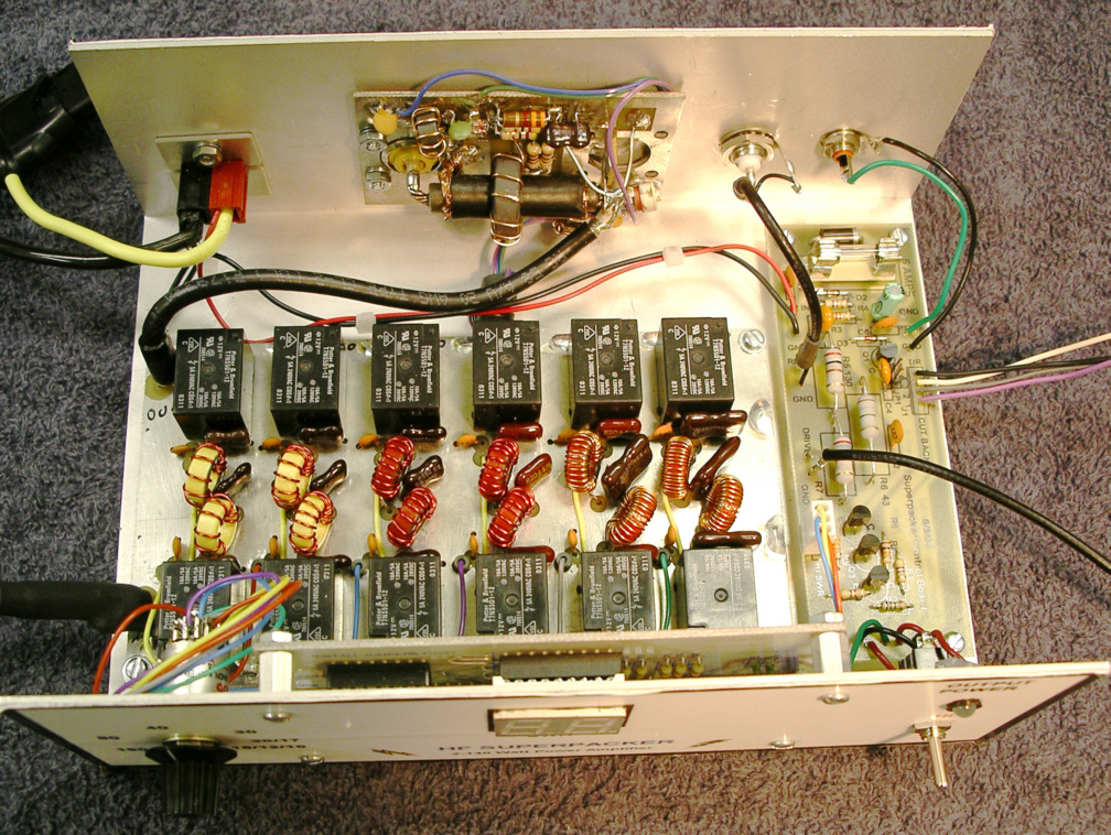
More photos
Close up of wiring in the lower half of the chassis
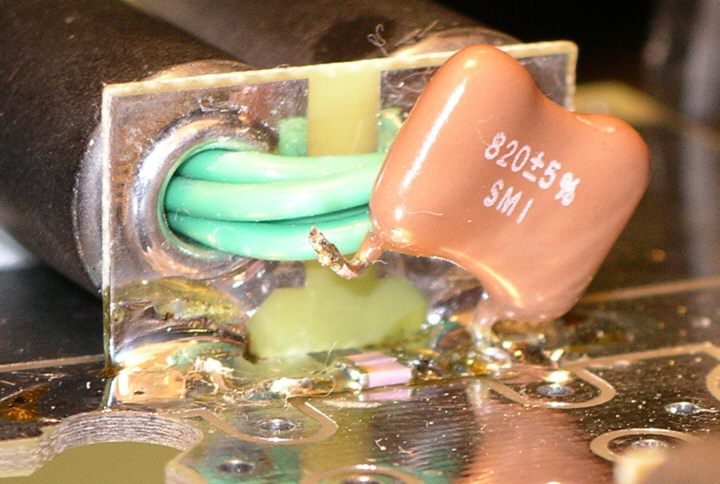
Close up of C6 (surface mount and through hole capacitors) on the CCI amplifier
Credits:
Thanks to:
Chuck W4MIL
last updated: 20 May 2006